Viper User
Manual (001-5008-000 Rev6)
Page
41
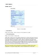
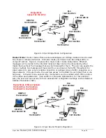
Viper can support up to 4 diagnostics socket connections at once. This may be used, for
instance, to carry out monitoring at a main office and at up to three separate field locations.
It is also possible one of the four connections use a serial port instead by enabling it on the
Viper’s web browser interface.
Output Format
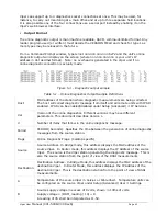
The online diagnostic output is man/machine readable, ASCII, comma-delimited format. Any
reader program used (or written) must decode the VERSION FIELD and check for type 1 as
more types may be released in the future.
From a Command Prompt window, type
telnet nnn.nnn.nnn.nnn 6272
and the unit’s online
diagnostic output will display on the screen (where nnn.nnn.nnn.nnn is your unit’s IP
address in dot decimal format). Note: no overhead is generated in the Viper unit if no
online diagnostic connection is actually made.
Figure 5.3 – Diagnostic output sample
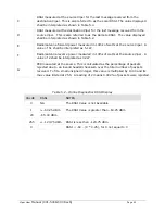
Table 5.1 – Online Diagnostics Output Sample Definitions
Host
MAC address of the station where diagnostic measurements are being collected.
The host will collect diagnostic message from itself and all remote units with IPSD
enabled. IPSD can be enabled/disabled under Setup (Advanced)
D
IP Services.
Ver
Version of the online diagnostics. Different versions may have different
parameters. This document describes Version 1.
#
Number of items that follow in the online diagnostic message.
Period
PERIOD (Seconds). Specifies the time between the generation of online diagnostic
messages from the source station.
Flags
Online Diagnostic Flags. (CalAmp specific)
Source
Source Address. In Bridge mode, this address displays the MAC address of the
source Viper. In Router mode, this address displays the IP Address of the source
Viper. The source is the Viper station generating the diagnostic message. This is
also the source station from the point of view of the RSSI measurements
Destination
Destination Address. In Bridge Mode, this address displays the MAC address of the
destination Viper. In Router Mode, this address displays the IP Address of the
destination Viper. This is the destination station from the point of view of RSSI
measurements.
A
Temperature of the source Viper in Celsius or Fahrenheit. Temperature units can
be configured on the source Viper under Setup (Advanced) User
D
Settings.
B
Source supply voltage in excess of 8 volts, shown in 10ths of volts.
Supply voltage = (ODM_reading / 10) + 8
A reading of 35 shall be interpreted as 11.5V.

