Viper User
Manual (001-5008-000 Rev6)
Page
13
PART NUMBERS AND AVAILABILITY
1.1.8
Viper Radio
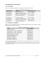
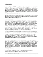
Table 1.5 provides a breakdown of the Viper part number 140-50X8-Y0Z.
Table 1.5 - Part Number Breakdown
Model Number
Description
Frequency Range
140-5018-500
Standard VHF Viper
136 - 174 MHz
140-5048-300
Standard UHF Viper Range 3
406.1 - 470 MHz
140-5048-500
Standard UHF Viper Range 5
450 – 512 MHz
140-5098-500
Standard 900MHz Viper
928 – 960 MHz
140-5018-501
Dual Port VHF Viper
136 - 174 MHz
140-5048-301
Dual Port UHF Viper Range 3
406.1 - 470 MHz
140-5048-501
Dual Port UHF Viper Range 5
450 – 512 MHz
140-5098-501
Dual Port 900MHz Viper
928 – 960 MHz
1.1.9
Accessories and Options
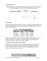
Tables 1.6-1.8 list standard accessories (including antenna, feedline, and connectors) tested
and approved for use with the Viper.
Table 1.6 - Accessories
ITEM
PART NUMBER
Viper Power Cable
897-5008-010
Viper Demo Kit* – VHF - 136-174 MHz
250-5018-500
Viper Demo Kit* – UHF - 406-470 MHz
250-5048-300
Viper Demo Kit* – UHF - 450-512 MHz
250-5048-500
Factory Installed Viper Fan Kit
150-5008-001
Field Installed Viper Fan Kit**
150-5008-002
TNC-Male to N-Male 18”
250-0697-103
TNC-Male to N-Male 48”
250-0697-104
TNC-Male to N-Male 72”
250-0697-105
TNC-Male to N-Female 18”
250-0697-106
* The Viper Demo Kit includes two of each of the following: Viper, rubber duck antennas, adapters, attenuators,
power cables, and power supplies.
** The field install Fan Kit is available for all UHF/900 Vipers (140-5048-xxx/140-5098-xxx) but is only available
for VHF models-(140-5018-xxx) with RF revision 0.3 or greater (shipping Fall 2008). Contact CalAmp Technical
Support for more information.

