xii
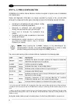
GENERAL VIEW
DS5100-X200
Serial Models
Figure A
1
Warning and Device Class Labels
7
Indicator LEDs
2
Power
– Serial Interfaces – I/O Cable
8
Network LEDs
with 25-pin D-sub connector
9
Power On LED
4
Laser Beam Output Window
10 Focus Adjustment Screw
5
Mounting Holes (7)
11 X-
PRESS™ Push Button
6
Display
10
11
2
4
7
9
8
6
5
1
5
Содержание DS5100
Страница 1: ......
Страница 29: ...RAPID CONFIGURATION 13 1 b Operating mode selection and definition a Digital Inputs configuration...
Страница 30: ...DS5100 REFERENCE MANUAL 14 1 b Digital Outputs configuration c Hardware interface selection...
Страница 62: ...DS5100 REFERENCE MANUAL 46 3 Figure 18 DS5100 OM Serial Model Overall Dimensions...
Страница 78: ...DS5100 REFERENCE MANUAL 62 4 Figure 38 ID NET Network Connections with isolated power blocks...
Страница 79: ...ELECTRICAL INSTALLATION 63 4 Figure 39 ID NET Network Connections with Common Power Branch Network...
Страница 80: ...DS5100 REFERENCE MANUAL 64 4 Figure 40 ID NET Network Connections with Common Power Star Network...
Страница 97: ...TYPICAL LAYOUTS 81 5 7 Double click on the DS5100 scanner to configure it...
Страница 163: ...147 X X PRESS Human Machine Interface 23...
Страница 164: ......


