background image

73 

MENU K 

– ALARMS & LIMITS (Service Level) - Custom Inputs


Alarm  Inputs


Custom  Alarm  Messages


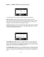
Alarm  #1   (DI-13)


SEE  TAG  INSIDE  DOOR


Alarm  #2   (DI-14)


SEE  TAG  INSIDE  DOOR


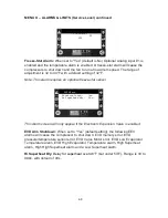
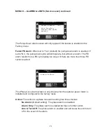
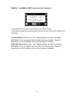
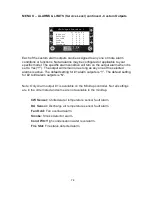
Each of the custom alarm inputs can be given a unique message that will appear 
on its alarm screen. Some messages also carry out a function as noted below. 
Additional sensors or switches may also be required. The selections are: 


SEE TAG INSIDE DOOR (default setting) 

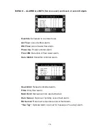
REHEAT INHIBITED 

– The reheat function is disabled. 

HUMIDIFIER INHIBITED 

– The humidifier function is disabled.


REHEAT & HUM INHIBITED 

– The reheat and humidifier functions are disabled. 

UNIT IN STBY 

– Not an alarm. Unit status screen will indicate “STANDBY”.


UPS ON-CHK MAIN PWR 

STANDBY PUMP ON


CHK HUMIDIFIER CYL


FAN MOTOR OVERLOAD - Inhibits heat and humidifier functions. 

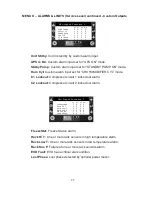
AE DAMPER NOT OPEN 

– See Airside Economizer Operation


AE DAMPER NOT CLOSED 

– See Airside Economizer Operation 

POWER A OPERATING 

– Message only, does not cause an alarm 

POWER B OPERATING 

– Message only, does not cause an alarm 

POWER A NOT AVAILABLE


POWER B NOT AVAILABLE 

COMPRESSOR VFD ALARM 

HUM FLT-CHK WTR PR


C1  HIGH  PRESSURE 

C2  HIGH  PRESSURE 

C1  LOW  PRESSURE 

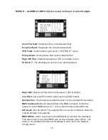
DIRTY FILTER


SMOKE DETECTOR 

– Alarm turns the unit off and remains active when unit is off. 

NO FLOW-CHECK PUMP


*Note: Some selections require optional equipment.


Содержание dap4 touch

Страница 1: ...1 dap4 User Manual Data Aire Inc 230 W BlueRidge Avenue Orange CA 92865 www dataaire com...

Страница 2: ...es the right to make design changes for the purpose of continuous product improvement or to withdraw any design without notice This manual was written when dap4 controllers were shipped with Software...

Страница 3: ...N Service Level 32 MENU H CALIBRATE SENSORS Service Level 34 MENU I MANUAL CONTROL Service Level 35 MENU J FACTORY SETTINGS Factory Level 36 MENU K ALARMS LIMITS Service Level 62 MENU L CONFIGURE I O...

Страница 4: ...ity Anticipation offsets the humidity set point to reduce excess humidification and dehumidification Options such as variable compressors and electronic expansion valves also contribute to energy savi...

Страница 5: ...its to assist with controlling temperature or airflow Inhibit control functions to prevent units from conflicting operations Primary and secondary schedules for economical control Unified zone airflow...

Страница 6: ...cated inside the electrical panel The display panel is mounted on the front door of the cabinet and or mounted in a remote location They are connected by a special telephone type cable Note If you nee...

Страница 7: ...n Touch Temp Hum readings to display the Set Points screen LED Unit Status White On Blue Cooling Green E Saver Red Alarm Power Key turns Unit on or off Color red unit is off Green unit is on Displays...

Страница 8: ...appear next to the icon to indicate multiple heaters are on If SCR or Hot Water heat type heat modulation is also shown Chilled Water Cooling On A number will also appear next to the icon to indicate...

Страница 9: ...ich displays the status of all optional rack sensor Note this screen does not appear if a rack sensor module is not used The highest or average depending on selection is shown on the top line followed...

Страница 10: ...enabled The next screen the Zone Units screen which displays the status of each units in the zone Note this screen only appears on Unit 1 when the Zone Control feature is enabled Touch the unit icon...

Страница 11: ...an optional power meter is installed The next screen in the status loop is the Variable Compressor Status screen Note this screen only appears when a variable compressor is installed The operating en...

Страница 12: ...r from running is shown in red text at the bottom of this screen The next screen in the status loop is the Trending screen It displays the historical trends of the return air temperature and humidity...

Страница 13: ...hing the Alarm icon on the main status screen The time and date of past alarms along with readings at the time of the alarm can be viewed Touch the Up or Down icon to see past alarm logs There will be...

Страница 14: ...de using the On Off Menu A The unit may be turned on or off by pressing the Power icon at the bottom left corner of the main screen The icon is green when unit is on and red when unit is off Once turn...

Страница 15: ...h Service or Factory level indicated at the top right of the screen Note These levels will expire if no key is pressed after 10 minutes Use the Up or Down key to move the menu of choice to appear in t...

Страница 16: ...able to change the Factory level password Note Be sure you write down any changes to these passwords and store in a safe and secure location MENU A ON OFF On Off Unit Start up Delay 5s Start up Mode...

Страница 17: ...each stage of DX cooling The range of adjustment is 0 3 to 3 0 F with a default of 0 3 F Latent Setpoint IRDX model only when set for discharge latent control mode in factory settings menu This setpoi...

Страница 18: ...mper can reopen Fixed Enthalpy mode This is the amount that the outside air enthalpy must drop below the inside air enthalpy before the damper can reopen The range of adjustment is 0 2 to 1 0 BTU with...

Страница 19: ...0 to 5 0 with a default value of 2 0 Dewpoint Setpoints Low Dewpoint Sp 45 0 Low Dewpoint Db 1 0 Hi Dewpoint Sp 59 0 Hi Dewpoint Db 1 0 Note This screen is only shown when humidity control is set to...

Страница 20: ...adjustment is 50 0 to 65 0 F with a default value of 59 0 F High Dewpoint Db This is the High Dewpoint Deadband It is the amount that the dewpoint must drop below setpoint before dehumidification ends...

Страница 21: ...r will start The range of adjustment is 1 to 15 with a default value of 3 Humidity Anticipation Hum Set Point 50 Temp Offset 2 Anticipation SP 48 values for ref only Note This screen is only shown whe...

Страница 22: ...ment is 40 0 to 85 0 F with a default value of 50 0 F Deadband The Energy Saver Deadband determines how much the chilled water temperature must drop below the setpoint for the energy saver mode to beg...

Страница 23: ...in when CO2 regulation is required Range of adjustment is 100 to 2000ppm with a default value of 1000ppm Deadband This is the amount CO2 may drop below the CO2 setpoint before the CO2 valve is modulat...

Страница 24: ...Time 4Hrs Important Notice Set Back should only be enabled for non critical applications where the unit may be turned off or the set points be changed without any damage to sensitive electronic equip...

Страница 25: ...85 F with a default value of 77 F If model is IRDX or CW only no DX maximum range increases to 105 F Heating Setpoint Temperature set point for heating used when the scheduler is in set back mode The...

Страница 26: ...on will remain until the next timed action for this day If it is the last timed action for this day it will remain effective until the next timed action of the following day The default value is to ta...

Страница 27: ...action settings No Action The scheduler will continue running the last action taken either this day or the previous day Normal SP Use the normal temperature and humidity settings This action will also...

Страница 28: ...ates are set Setting This is the action that should occur at the selected date This action will remain until the next start date that is set to have an action The default value is to take No Action Th...

Страница 29: ...e indicated by a black box Digital Outputs shown The status of the 18 relay outputs only 7 outputs on minidap4 are indicated on one screen Relay outputs in the on state are indicated by a black box An...

Страница 30: ...Date month day year format when this alarm occurred Scroll Up Down Use the UP key to view an older alarm if any or use the DOWN key to view a newer alarm The sequential number of the displayed alarm...

Страница 31: ...e 1 01 23 0 08 22 6 02 23 2 09 22 8 03 23 1 10 22 3 04 22 9 11 22 4 05 23 2 12 22 5 06 23 5 13 22 8 Note The power usage screens are only displayed when an optional power meter is installed and config...

Страница 32: ...d in milliseconds Information 3 Lists the Temperature near the processor The Power Supply Voltage The Power Supply current in milliamps EEV Driver Lists information about the electronic expansion valv...

Страница 33: ...32 MENU F INFORMATION differently from what is written in this manual...

Страница 34: ...and automatically turn on if there are no other conditions will keep it off To ensure reliable operation with the BMS the heartbeat point should be toggled 0 1 or 1 0 at least once a minute Note The...

Страница 35: ...fluence on the supervisory BMS network Immediately after setting this address the terminal configuration of the controller will also change Consequently the display s address must also be changed for...

Страница 36: ...a calibrated instrument Each screen in this menu identifies the function of the sensor and the terminal that the sensor is connected to Offset The amount that the sensor needs to be corrected by so th...

Страница 37: ...e to Manual mode the Return to Auto timer for that output is started When the timer expires the output will return to automatic mode value which is determined by the dap4 logic Note The controller doe...

Страница 38: ...intain the Return default or Discharge temperature referred to as the control temperature Out Status not on MiniDAP This Setting determines what controls the Status Output relay DO7 Choices are System...

Страница 39: ...oint Const Flow Fan modulates to maintain the airflow set point BMS Flow Fan modulates to maintain the airflow setpoint of the BMS Vlv Pos Flow Fan modulates to maintain the airflow based on CW valve...

Страница 40: ...erature to maintain temp set point Mod to RetT Shown only on IRDX model Fan will modulate to the return air temperature to maintain the fan temperature set point Note on Return and Rack temperature se...

Страница 41: ...Damper is enabled Sets the fan speed when unit is in standby mode This feature can be used to prevent backdraft from pressure in the discharge duct Range of adjustment is 10 to 50 with a default sett...

Страница 42: ...ffectively the sensitivity of the algorithm The smaller the band the more the algorithm will try to correct the error If the band setting is too low the system will oscillate by being over responsive...

Страница 43: ...a default of 348 Minimum Flow The lowest airflow setting that the fans should produce Range of adjustment is 0 to 32000cfm with a default setting of 2000cfm Maximum Flow The highest airflow setting t...

Страница 44: ...If Integral time setting is too long the fan speed may become sluggish to change A setting of 0s puts the algorithm in a proportional only mode Range of adjustment is 0 to 999s with a default setting...

Страница 45: ...ensitivity of the algorithm The smaller the band the more the algorithm will try to correct the error If the band setting is too low the system will oscillate by being over responsive If the band sett...

Страница 46: ...his dead band for temperature critical applications The use of SCR heating is recommended Caution Use of the precision mode will likely cause energy inefficiency and may be prohibited in some areas DX...

Страница 47: ...ssor will modulate in speed to maintain the discharge air temperature D T Var Latent Compressor will modulate in speed to maintain the discharge air temperature based on the calculated latent set poin...

Страница 48: ...temperature reading and set point The higher Integral time setting the slower the compressor speed will change If the Integral time is set too low the compressor speed could change quickly causing os...

Страница 49: ...unt that the temperature must drop below Setpoint before C2 is turned off Range of adjustment is 0 to 9 9 F with a default of 1 0 F C1 Boost Time When C2 turns off C1 modulation is limited to be no lo...

Страница 50: ...large amount of refrigerant dilutes the compressor lubrication resulting in damage to the compressor Suction Pressure The current suction pressure for reference only Cut Out SP The suction pressure mu...

Страница 51: ...e is the lead Rotation is by FIFO Only displayed when there are four compressors FIFO means that the first compressor started will also be the first compressor to stop Rotate Lead displayed when there...

Страница 52: ...ure of the discharge air during dehumidification only HGRH 1 Like HGRH mode but has an additional electric heat output HT3 DO11 that turns on when temperature drops below setpoint minus heat dead band...

Страница 53: ...ly shift the HGRH valve opening to correct the error between temperature reading and set point The higher Integral time setting the slower the valve will be changed If the Integral time is set too low...

Страница 54: ...signal voltage used for the installed water valve Choices are 0 10 2 10 7 10 6 9 and 4 7 volts Note Selections below are only displayed in Engy Svg or Aux Chill Wtr modes E S Assist The number of com...

Страница 55: ...54 MENU J FACTORY SETTINGS factory level continued compressors regardless of the air temperature...

Страница 56: ...on will be 100 when temperature equals setpoint band Range of adjustment is 0 5 to 25 0 F with a default of 3 0 F Integration Time Used to incrementally change the CW valve modulation as a result of a...

Страница 57: ...or the length of this delay Once the compressor s have started the CW valve will be forced 100 open Range of adjustment is 0 to 60 minutes with a default of 2 mins DX CW Delay When compressors have tu...

Страница 58: ...on Mod On Off humidity control with reheat which is used to maintain temperature control Auto Flush Not shown on MiniDAP This selection sets how many hours can elapse before the humidifier pan drain i...

Страница 59: ...set point minus the dead band Dehumidification will resume when the temperature rises back to the set point 4C No Limit Four compressors may run regardless of temperature Reheat Limit Choice to limit...

Страница 60: ...NSI where the equipment is installed see map below It determines the maximum Outside Air Temperature that the economizer can operate Normally this setting should not be changed Mode Modulation of damp...

Страница 61: ...d This setting determines the sensitivity of the algorithm The smaller the band the more the algorithm will try to correct the error If the band setting is too low the damper actuator may oscillate by...

Страница 62: ...ed by the module Note An external rack sensor module is required when more than 1 sensor is selected 3 sensors on IRDX and IRCW models Use the Options Installed screen to select the type of external m...

Страница 63: ...rol Alarm B 06 Control Alarm B Note The Rack Settings screens are only displayed when the rack mode is enabled Select a function for each installed sensor and which group if groups are used that the s...

Страница 64: ...rent settings from another dap4 to be uploaded so it will be a copy of that controller Note Use of this feature will remove the Zone Control and or Airside Economizer password keys from the controller...

Страница 65: ...tion There will be no alarm and startup as normal Auto With Alm There will be an alarm and startup as normal Man Clr Alarm There will be an alarm and controller will not startup until the alarm is ack...

Страница 66: ...of a short cycle condition Floor Water Alarm Action This is the setting of what should happen if floor water is detected The floor water alarm cannot be disabled The selections for the alarm action a...

Страница 67: ...on the no water flow alarm screen Lockout CW The CW cooling will be locked out for ES Lockout Time before CW cooling will be allowed to function again A countdown showing the time remaining until CW...

Страница 68: ...run at the maximum speed setting plug fan only The range of set point adjustment is 70 to 90 F 70 to 120 F on CW units with a default setting of 80 F Lo Temp Alarm When set to Yes default the alarm i...

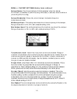
Страница 69: ...66 MENU K ALARMS LIMITS Service Level continued Control Only...

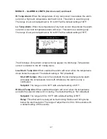
Страница 70: ...ge Temp Alarm screen will only appear if a Discharge Temperature sensor is enabled in the I O Config menu Low Disch Temp Alm When enabled the alarm will occur when the temperature drops below the setp...

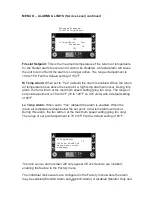
Страница 71: ...setpoint high before lockout occurs The range of adjustment is 5 to 300 seconds with a default of 30 seconds Humidity Alarms Hi Humidity Alarm Yes Setpoint 60 Lo Humidity Alarm Yes Setpoint 40 Hi Hum...

Страница 72: ...es an optional freeze stat sensor EEV Alarm Shutdown Comps Yes Hi Superheat dly 90s This Alarm screen will only appear if the Electronic Expansion Valve is enabled EVD Alm Shutdown When set to Yes def...

Страница 73: ...ted by a factory technician Start Up Delay This delay blocks the out of envelope alarm when the compressor starts Range of adjustment is 15 180 seconds with a default setting of 100 seconds Run Outsid...

Страница 74: ...an alarm The PD alarm results from a PD cycle taking too long or if there are more than three PD cycles required Phase Loss Alarm Action No Alarm This Phase Loss Alarm screen is only shown when the op...

Страница 75: ...the unit functions from operating Low CO2 Alarm When set to Yes default setting the alarm is enabled Set Point This is the lowest CO2 level that will cause an alarm Range of adjustment is 100 to 5000p...

Страница 76: ...TED The reheat and humidifier functions are disabled UNIT IN STBY Not an alarm Unit status screen will indicate STANDBY UPS ON CHK MAIN PWR STANDBY PUMP ON CHK HUMIDIFIER CYL FAN MOTOR OVERLOAD Inhibi...

Страница 77: ...e output alarm when it is set to Yes Y The output will remain on as long as any one of the selected alarms is active The default setting for 1 alarm outputs is Y The default setting for 2 to 4 alarm o...

Страница 78: ...Low Pr Circuit 2 low pressure alarm Short Cycl One or more compressors has caused a short cycle alarm Maint Timer Maintenance timer alarm Alm Output Function 3 1 2 3 4 Hi Humid Y N N N Low Humid Y N...

Страница 79: ...p Power restored alarm Floor Wtr Detection of floor water alarm Hum Inhibit Humidifier inhibited alarm Alm Output Function 5 1 2 3 4 Heat Inhbt Y N N N Filter Y N N N Manl Ovrd Y N N N Hum Sensor Y N...

Страница 80: ...nput set for CHK HUMIDIFIER CYL mode C1 Lockout Compressor circuit 1 locked out alarm C2 Lockout Compressor circuit 2 locked out alarm Alm Output Function 7 1 2 3 4 FreezeStat Y N N N Rack Hi T Y N N...

Страница 81: ...2 3 4 CO2 High Y N N N CO2 Low Y N N N Damper Pos Y N N N BMS Command Y N N N A E Avail Y N N N BMS Offline Y N N N High CO2 High level CO2 alarm only used on gPOD model Low CO2 Low level CO2 alarm on...

Страница 82: ...78...

Страница 83: ...s Indicates the current status of the switch connected to the input Analog Input Humidity Sensor Enable On Channel U01 Normal 4 20mA Minimum 0 0 Maximum 100 0 Offset 0 0 Value 51 1 Analog Input Screen...

Страница 84: ...one Humidity Outside Temp Outside Hum Disc Pressure Suct Pressure Diff Pressure Pressure Flow Supply Hum FreezeStat Temp Hot Gas Temp Room Temp Room Hum Damper Pos Valve Position Note FreezeStat Temp...

Страница 85: ...he standby mode Primary or Secondary Schedule Selecting a secondary schedule offers even greater flexibility so that units can have different modes based on a time schedule Number Units On This settin...

Страница 86: ...rflow set point for the zone in cubic feet per minute This set point is the same one that appears on the Zone Airflow screen in the set points loop Integration Time This setting determines the time be...

Страница 87: ...o 10 0 degrees default of 1 3 instead of the fixed 1 3 F threshold that is added to DX staging when energy saver is running Standby On Delay This is how long Unit 1 will wait before requesting a stand...

Страница 88: ...me increment beginning from when the increment is selected It is not based on the clock hour status Range is 1 to 48 Hrs Exercise U2 Only shown when two units are installed This setting is used for ap...

Страница 89: ...1 modulate the fans greater than this setting additional standby units may be requested to assist 4 To fill in for another unit that has an alarm based on selections for Standby Alarms described later...

Страница 90: ...screens are in military 24 hour format Example 6 00 PM 18 00 Day This is the selection of the weekday that you are currently configuring Copy to This selection allows you to copy the settings of the d...

Страница 91: ...h to end the holiday Setting Choose which schedule will run during the holiday When the clock reaches the selected start day at 12 00 midnight the schedule that is selected will run When the clock rea...

Страница 92: ...e to report selected alarms to Unit 1 Based on the alarm selection Unit 1 will act as described below There are up to 35 types of alarms that can be chosen Only the DX Off by Alm Stby setting is defau...

Страница 93: ...lates to maintain the airflow set point BMS Flow Fan modulates to maintain the airflow setpoint of the BMS Vlv Pos Flow Fan modulates proportionally to the CW valve position Return Air T Fan modulates...

Страница 94: ...actory menu fan range settings screen Allows the fan to run at a low speed when unit is in standby mode The standby speed modulation is not limited by the Modulation Min setting This feature can be us...

Страница 95: ...ture is below the energy saver set point minus dead band During this time E S Avail is displayed piggybank icon on touch display Should the chilled water temp rise above the energy saver set point a C...

Страница 96: ...unit is on but no CW cooling has occurred for 100hrs the CW valve will be opened 100 for a period of 60 seconds Safeties for CW Cooling The CW valve will close under the following conditions Condensat...

Страница 97: ...Gas Temp Alarm High Superheat Alarm over 48 F delayed High High Superheat Alarm over 54 F no delay Low Superheat Alarm under 4 F EVD valve motor alarm Timing Safeties Once a compressor is turned off f...

Страница 98: ...erature Setpoint Stage to Stage X 3 Stage 3 OFF at Temperature Setpoint Stage to Stage X 2 Stage 2 OFF at Temperature Setpoint Stage to Stage Stage 1 OFF at Temperature Setpoint Note The Stage to Stag...

Страница 99: ...r temperature drops below the Setpoint C1 Off The variable compressor turns off when temperature drops below the Setpoint minus the C1 Offset setting default of 1 0 F for the duration of the C1 Off De...

Страница 100: ...for the duration of the C2 Off Delay time setting However the compressor must finish the minimum run time setting before it can turn off In anticipation of loss in cooling from turning C2 off the vari...

Страница 101: ...he Setpoint minus the C2 Offset setting default of 1 0 F for the duration of the C2 Off Delay time setting However the compressor must finish the minimum run time setting before it can turn off In ant...

Страница 102: ...DO9 turns on when temperature drops below setpoint minus the Stage To Stage setting Enable SCR for supplemental electric reheat HGRH 1 Like HGRH mode but has an additional electric heat output HT3 DO...

Страница 103: ...en the last compressor stopped cooling to when heating may begin This delay is called the Dly After DX in Factory settings menu and is defaulted to 10mins There is a 60 second delay between each heati...

Страница 104: ...eat may lack responsiveness Ideally the band setting should be as low as possible without causing oscillation The Integration time setting is used to slowly shift the HGRH valve opening to correct the...

Страница 105: ...Water alarm Condensation Alarm or a Dehumidification Inhibit command from BMS Timed Safeties Dehumidification mode cannot run within 5 minutes of a humidification cycle Temperature Safeties When Dehu...

Страница 106: ...y run regardless of temperature drop Reheat Limit Choice to limit how many compressors can run in dehum mode when electric reheat turns on not HGRH or Hot Water reheat Choices are 1 Comp default selec...

Страница 107: ...at High DP Setpoint minus DP DB Stage 1 OFF at High DP Setpoint minus DP DB minus 0 2 F Four Compressor staging as dewpoint is increasing Stage 1 ON at High DP Setpoint minus 0 6 F Stage 2 ON at High...

Страница 108: ...ach 2 increase in humidity and reach 100 at Humidity Setpoint Deadband 2 As humidity decreases the compressor demand will decrease to zero and turn off at Humidity Setpoint Temp Control set to Dischar...

Страница 109: ...idification mode starts when humidity drops below the Humidity Setpoint minus 1 As humidity drops the humidifier demand will rise proportionally to reach 100 at setpoint minus deadband As humidity ris...

Страница 110: ...the setpoint to a maximum 10 offset The amount of offset is shown in a screen dedicated to this mode in the set points menu Safeties Humidification will not run under the following conditions Humidif...

Страница 111: ...mand for cooling airflow or static air pressure To even out run time between units Unit 1 has a rotation schedule that will change which unit is in the lead Beginning with the lead unit additional uni...

Страница 112: ...suring sensor to be installed An additional airflow tuning screen will appear in the Zone Control menu allowing you adjust the airflow set point and tune the airflow modulation Unity Cooling Allows a...

Страница 113: ...rees default of 1 3 instead of the fixed 1 3 F threshold that is added to DX staging when energy saver is running Standby On Delay This is how long Unit 1 will wait before requesting a standby unit to...

Страница 114: ...d on the unit that had the alarm it may to turn back on and return the requested unit may return to standby Priority mode operates the same as the standby mode described above except it has priority i...

Страница 115: ...ormat Time and Setting Set the time of day when the schedules should change Then set which schedule should be run at the time selected Primary or Secondary When the clock reaches the time set the sche...

Страница 116: ...ed WARNING There is no intent on the part of Data Aire Inc to define local codes and statutes which may supersede common trade practices nor do we assume responsibility for their interpretation Consul...

Страница 117: ...e temperature drops more than 5 F below setpoint Please refer to the section Operation of DX Cooling for information regarding when the compressors will run in the energy saver mode Economizer Modes F...

Страница 118: ...mper Setting to maintain the temperature setpoint High OA Temp In Differential Dry Bulb mode The OA temperature must be lower than the inside Return Air Temperature If the OA temperature is greater th...

Страница 119: ...r to verify its position An Optional Analog input must be set to Damper Position to enable the alarm and set to the type of sensor that is being used in I O Config menu The position feedback of the se...

Страница 120: ...cation Possible Causes Corrective Actions Chilled Water Sensor Failure Chilled water sensor failure detected Warning Chilled Water Sensor input is enabled but no sensor is connected Loose Connection F...

Страница 121: ...Incorrect settings of digital input on the controller Blow out or clean drain line Replace condensate pump Check and replace float switch Check wire connections Check vertical drain line Lift The high...

Страница 122: ...test for leaks Repair leaks and add refrigerant Adjust and check valve operation and replace if needed Replace filter drier Repair restriction Check line design at IOM Test compressor efficiency Go t...

Страница 123: ...sure switch Compressor Short Cycle Compressor has started more than 10 times in an hour Urgent Not enough Heat Load or Oversized System Temperature Dead Band is set too low Humidity Dead Band is too l...

Страница 124: ...nsor replace if needed Humidifier failure Humidifier malfunction Warning Low water pressure Overcurrent detected or no current Fill system failure End of cylinder life Incorrect settings of digital in...

Страница 125: ...Temp Return Air Temperature is below alarm set point limit Warning Return air temperature is too low Not enough heat load Faulty Sensor Loose Connection Out of calibration Increase Temperature set poi...

Страница 126: ...put on the controller Switch Manual Override switches to off position Go to Menu L Configure I O and change Manual Override Switch action setting Air Flow No Airflow detected Urgent No air flow Speed...

Страница 127: ...ction Module Go To I O Input in Menu L Floor Water Switch and change the Action Humidity Inhibited Humidification mode is prohibited from running Warning Optional alarm input switch is configured to i...

Страница 128: ...ntroller Check connection Use sensor chart to check sensor signal in milliamps Replace sensor if required Connect wiring to correct connection points Go to Menu L Configure I O and check the Humidity...

Страница 129: ...e controller Using wiring diagram to check wiring of humidifier cylinder and humidifier controller Go to Menu L Configure I O and change the Humidifier Fault Switch action setting C1 or C2 Lockout Com...

Страница 130: ...ck input signal to compressor speed control and the compressors actual speed Check temperature set point and compressors mode of operation Discharge or Return control Check fan speed control and set p...

Страница 131: ...m occurs it may cause the VFD alarm to happen as well Resolve this by focusing on the cause of the Low or High pressure alarm Pump Down Exceeded Maximum Time or Count Compressor failed to Pump Down Ur...

Страница 132: ...n sensor does not match the modulated position Warning The modulated position sent to the damper actuator is not within 10 of the position sensor reading Check damper position sensor reading in closed...

Страница 133: ...129 Wiring Connections...

Страница 134: ...t 1 NO9 J16 2 TB1 7 Reheat 2 NO10 J16 3 TB1 20 Reheat 3 NO11 J16 4 TB1 21 Alarm 3 function is selectable NO12 J17 1 TB1 45 C12 J17 2 TB1 43 NC 12 J17 3 TB1 44 Alarm 4 function is selectable Light Sens...

Страница 135: ...m Deg F Kohm Deg F Kohm 32 00 27 28 51 80 17 24 71 60 11 20 91 40 7 45 111 20 5 08 33 80 26 13 53 60 16 55 73 40 10 78 93 20 7 19 113 00 4 91 35 60 25 03 55 40 15 90 75 20 10 38 95 00 6 94 114 80 4 74...

Страница 136: ...a defined by the evaporator and condenser temperatures that the compressor is designed to run EVD Electronic Valve Driver that is used to control an electrical expansion valve gPOD Is a model that is...

Страница 137: ...dataaire com Sales dataaire com Fax 714 921 6010 Main 714 921 6011 Engineering 714 921 6022 Parts Sales Web Site www dataaire com Job Unit Information Data Aire Job Number Serial Number _ Model Number...

Отзывы: