


Motor rotation check can be performed using par. 1-28
and following the steps shown in the display.
F frame Requirements
F1/F3 requirements: Motor phase cable quantities must be multiples
of 2, resulting in 2, 4, 6, or 8 (1 cable is not allowed) to obtain equal
amount of wires attached to both inverter module terminals. The cables
are required to be equal length within 10% between the inverter mod-
ule terminals and the first common point of a phase. The recommen-
ded common point is the motor terminals.
F2/F4 requirements: Motor phase cable quantities must be multiples
of 3, resulting in 3, 6, 9, or 12 (1 or 2 cables are not allowed) to obtain
equal amount of wires attached to each inverter module terminal. The
wires are required to be equal length within 10% between the inverter
module terminals and the first common point of a phase. The recom-
mended common point is the motor terminals.
Output junction box requirements: The length, minimum 2.5 me-
ters, and quantity of cables must be equal from each inverter module
to the common terminal in the junction box.
NB!
If a retrofit applications requires unequal amount of
wires per phase please consult the factory for re-
quirements and documentation or use the top/
bottom entry side cabinet option.
4.1.8 Brake Cable Drives with Factory Installed Brake Chopper Option
(Only standard with letter B in position 18 of typecode).
The connection cable to the brake resistor must be screened and the
max. length from frequency converter to the DC bar is limited to 25m
(82ft).
Terminal No.
Function
81, 82
Brake resistor terminals
The connection cable to the brake resistor must be screened. Connect
the screen by means of cable clamps to the conductive back plate at
the frequency converter and to the metal cabinet of the brake resistor.
Size the brake cable cross-section to match the brake torque. See also
Brake Instructions, MI.90.Fx.yy
and
MI.50.Sx.yy
for further information
regarding safe installation.
Please note that voltages up to 1099 VDC, depending
on the supply voltage, may occur on the terminals.
F Frame Requirements
The brake resistor(s) must be connected to the brake terminals in each
inverter module.
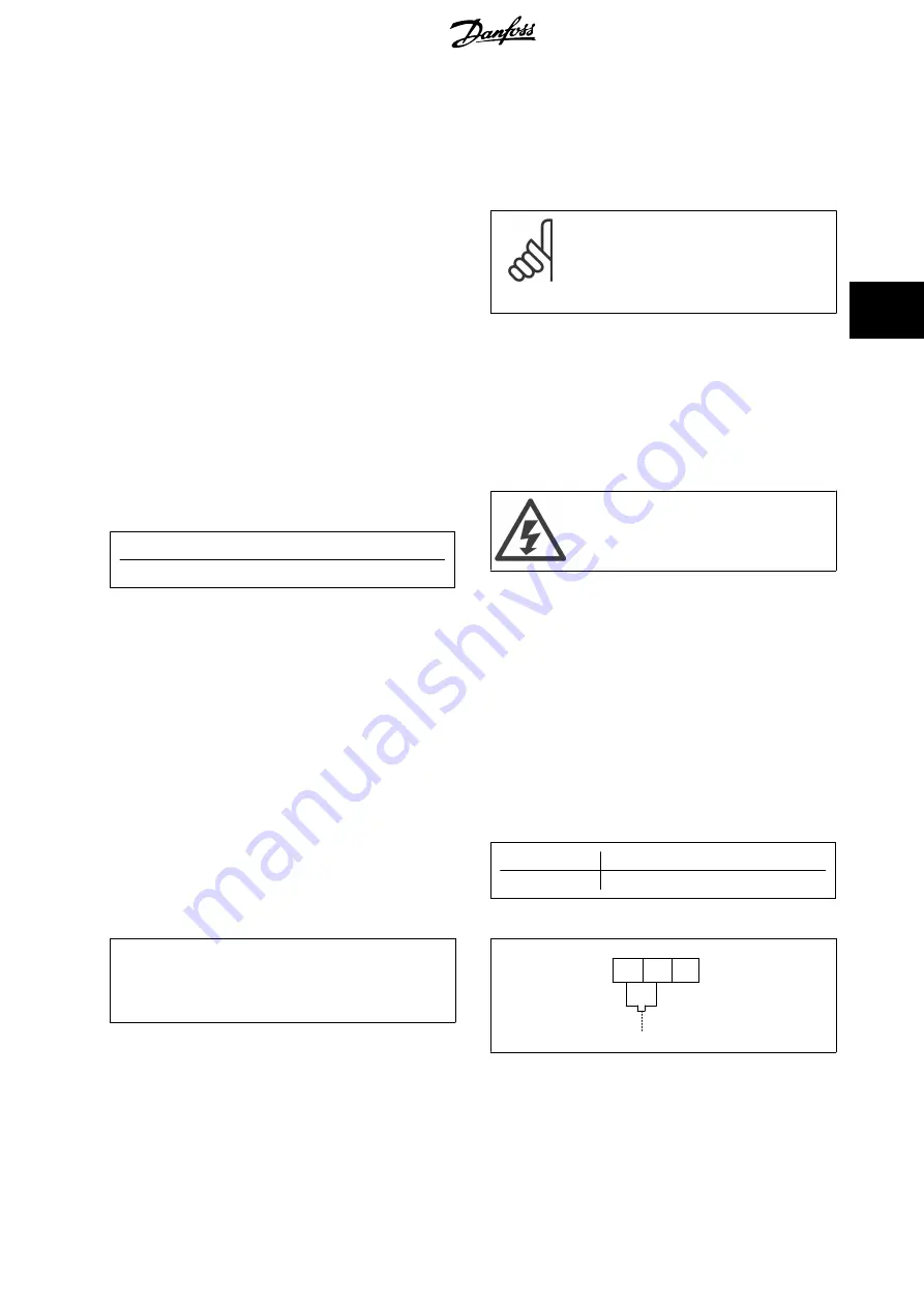
4.1.9 Brake Resistor Temperature Switch
Frame size D-E-F
Torque: 0.5-0.6 Nm (5 in-lbs)
Screw size: M3
This input can be used to monitor the temperature of an externally
connected brake resistor. If the input between 104 and 106 is estab-
lished, the frequency converter will trip on warning / alarm 27, “Brake
IGBT”. If the connection is closed between 104 and 105, the frequency
converter will trip on warning / alarm 27, “Brake IGBT”.
A KLIXON switch must be installed that is `normally closed'. If this
function is not used, 106 and 104 must be short-circuited together.
Normally closed: 104-106 (factory installed jumper)
Normally open: 104-105
Terminal No.
Function
106, 104, 105
Brake resistor temperature switch.
If the temperature of the brake resistor gets too high
and the thermal switch drops out, the frequency
converter will stop braking. The motor will start
coasting.
175ZA877.10
106
NC
104
C
105
NO
VLT HVAC Drive High Power Operating In-
structions
4 Electrical Installation
MG.11.F3.02 - VLT
®
is a registered Danfoss trademark
63
4