13 Disposal
Installer reference guide
88
ERGA04~08DAV3(A) + EHVH/X04+08S18+23DA
Daikin Altherma – Low temperature split
4P495248-1 – 2017.12
DANGER: RISK OF EXPLOSION
Pump down – Refrigerant leakage.
If you want to pump
down the system, and there is a leakage in the refrigerant
circuit:
▪ Do NOT use the unit's automatic pump down function,
with which you can collect all refrigerant from the
system into the outdoor unit.
Possible consequence:
Self-combustion and explosion of the compressor
because of air going into the operating compressor.
▪ Use a separate recovery system so that the unit's
compressor does NOT have to operate.
NOTICE
During pump down operation, stop the compressor before
removing the refrigerant piping. If the compressor is still
running and the stop valve is open during pump down, air
will be sucked into the system. Compressor breakdown or
damage to the system can result due to abnormal pressure
in the refrigerant cycle.
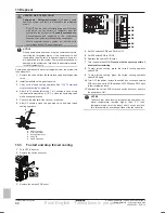
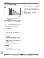
Pump down operation will extract all refrigerant from the system into
the outdoor unit.
1
Remove the valve lid from the liquid stop valve and the gas stop
valve.
2
Install a manifold on the gas stop valve.
3
Carry out the forced cooling operation. See
"13.3 To start and
stop forced cooling" on page 88
.
4
After 5 to 10 minutes (after only 1 or 2 minutes in case of very
low ambient temperatures (<−10°C)), close the liquid stop valve
with a hexagonal wrench.
5
Check on the manifold if the vacuum is reached.
6
After 2-3 minutes, close the gas stop valve and stop forced
cooling operation.
a
c
b
d
d
e
a
Gas stop valve
b
Closing direction
c
Hexagonal wrench
d
Valve lid
e
Liquid stop valve
13.3
To start and stop forced cooling
1
Turn OFF the power.
2
Remove the switch box cover.
2×
3
Remove the service PCB cover.
1 2 3
L
N
L N PWR
HEAT
COOL
4
3
2
1
2
1
E
D
C
B
A
A
1
2
3
4
5
SW1
SW3
SW2
SW5
SW6
SW4
S501
S502
S2
1×
4
Set DIP switches SW5 and SW6 to OFF.
5
Set DIP switch SW2 to COOL.
6
Reattach the service PCB cover.
7
Turn the power back ON.
Proceed with the next step within 3
minutes after restarting.
8
To start forced cooling, press the forced cooling operation
switch SW1.
9
To stop forced cooling, press the forced cooling operation
switch SW1 again.
10
Turn OFF the power, remove the switch box cover and service
PCB cover and set the DIP switches SW5, SW6 and SW2 back
to their original position.
11
Reattach the service PCB cover and switch box cover and turn
the power back ON.
NOTICE
Take care that while running forced cooling operation, the
water temperature remains higher than 5°C (see
temperature read out of the indoor unit). You can achieve
this, for example, by activating all fans of the fan coil units.
Final English - Tanslations in progress

