background image

7 Installation

Installer reference guide

36

ERGA04~08DAV3(A) + EHVH/X04+08S18+23DA

Daikin Altherma – Low temperature split

4P495248-1 – 2017.12

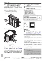
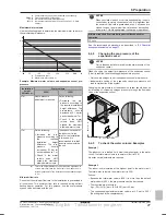
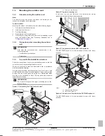
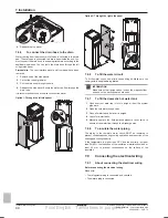
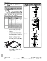
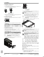
To open/close the stop valve

1

Remove the stop valve cover.

2

Insert a hexagonal wrench (liquid side: 4 mm, gas side: 4 mm)
into the valve stem and turn the valve stem:

Counterclockwise to open.
Clockwise to close.

3

When  the  stop  valve  CANNOT  be  turned  any  further,  stop
turning. The valve is now open/closed.

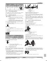
To handle the stem cap

▪ The  stem  cap  is  sealed  where  indicated  with  the  arrow.  Do  NOT

damage it.

▪ After handling the stop valve, tighten the stem cap, and check for

refrigerant leaks.

Item

Tightening torque (N∙m)

Stem cap, liquid side

13.5~16.5

Stem cap, gas side

22.5~27.5

To handle the service cap

▪ ALWAYS use a charge hose equipped with a valve depressor pin,

since the service port is a Schrader type valve.

▪ After  handling  the  service  port,  tighten  the  service  port  cap,  and

check for refrigerant leaks.

Item

Tightening torque (N∙m)

Service port cap

11.5~13.9

7.5.8

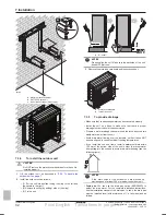
To connect the refrigerant piping to the
outdoor unit

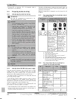
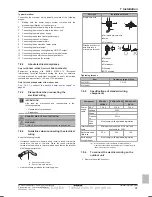
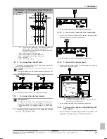
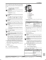
1

Connect the liquid refrigerant connection from the indoor unit to
the liquid stop valve of the outdoor unit.

a

b

c

a

Liquid stop valve

b

Gas stop valve

c

Service port

2

Connect  the  gas  refrigerant  connection  from  the  indoor  unit  to
the gas stop valve of the outdoor unit.

NOTICE

It  is  recommended  that  the  refrigerant  piping  between
indoor  and  outdoor  unit  is  installed  in  a  ducting  or  the
refrigerant piping is wrapped with finishing tape.

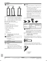
7.5.9

To connect the refrigerant piping to the
indoor unit

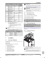
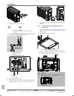
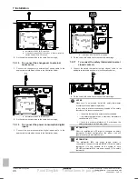
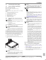
1

Connect  the  liquid  stop  valve  from  the  outdoor  unit  to  the
refrigerant liquid connection of the indoor unit.

b

a

a

Refrigerant liquid connection

b

Refrigerant gas connection

2

Connect  the  gas  stop  valve  from  the  outdoor  unit  to  the
refrigerant gas connection of the indoor unit.

NOTICE

It  is  recommended  that  the  refrigerant  piping  between
indoor  and  outdoor  unit  is  installed  in  a  ducting  or  the
refrigerant piping is wrapped with finishing tape.

INFORMATION

When  the  indoor  unit  is  installed  in  a  place  with  limited
space,  an  optional  pipe  bend  (EKHVTC)  kit  can  be
installed  to  facilitate  the  connection  to  the  refrigerant  gas
and  liquid  connections  of  the  indoor  unit.  For  installation
instructions, see the instruction sheet of the pipe bend kit.

7.6

Checking the refrigerant piping

7.6.1

About checking the refrigerant piping

The outdoor unit's 

internal

 refrigerant piping has been factory tested

for  leaks.  You  only  have  to  check  the  outdoor  unit's 

external

refrigerant piping.

Before checking the refrigerant piping

Make  sure  the  refrigerant  piping  is  connected  between  the  outdoor
unit and the indoor unit.

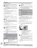
Typical workflow

Checking  the  refrigerant  piping  typically  consists  of  the  following
stages:

1

Checking for leaks in the refrigerant piping.

2

Performing  vacuum  drying  to  remove  all  moisture,  air  or
nitrogen from the refrigerant piping.

Final English - Tanslations in progress

Содержание EHVH04S18DA6V

Страница 1: ... temperature split ERGA04DAV3 A ERGA06DAV3 A ERGA08DAV3 A EHVH04S18DA6V G EHVH04S23DA6V G EHVH08S18DA6V G EHVH08S23DA6V G EHVH08S18DA9W G EHVH08S23DA9W G EHVX04S18DA3V G EHVX04S18DA6V G EHVX04S23DA3V G EHVX04S23DA6V G EHVX08S18DA6V G EHVX08S23DA6V G EHVX08S18DA9W G EHVX08S23DA9W G Final English Tanslations in progress ...
Страница 2: ... Refrigerant piping insulation 25 6 4 Preparing water piping 25 6 4 1 Water circuit requirements 25 6 4 2 Formula to calculate the expansion vessel pre pressure 26 6 4 3 To check the water volume and flow rate 26 6 4 4 Changing the pre pressure of the expansion vessel 27 6 4 5 To check the water volume Examples 27 6 5 Preparing electrical wiring 28 6 5 1 About preparing electrical wiring 28 6 5 2 ...

Страница 3: ...9 10 Hand over to the user 80 11 Maintenance and service 80 11 1 Overview Maintenance and service 80 11 2 Maintenance safety precautions 80 11 3 Checklist for yearly maintenance of the outdoor unit 80 11 4 Checklist for yearly maintenance of the indoor unit 81 11 4 1 To drain the domestic hot water tank 82 11 5 About cleaning the water filter in case of trouble 82 11 5 1 To remove the water filter...

Страница 4: ...mal temperature If you must touch it wear protective gloves Do NOT touch any accidental leaking refrigerant WARNING Provide adequate measures to prevent that the unit can be used as a shelter by small animals Small animals that make contact with electrical parts can cause malfunctions smoke or fire CAUTION Do NOT touch the air inlet or aluminium fins of the unit NOTICE Do NOT place any objects or ...

Страница 5: ...harged after performing the leak test and the vacuum drying In case re charge is required refer to the nameplate of the unit It states the type of refrigerant and necessary amount The unit is factory charged with refrigerant and depending on pipe sizes and pipe lengths some systems require additional charging of refrigerant Only use tools exclusively for the refrigerant type used in the system thi...

Страница 6: ...rter resistant to high frequency electric noise to avoid unnecessary opening of the earth leakage protector NOTICE Precautions when laying power wiring Do NOT connect wiring of different thicknesses to the power terminal block slack in the power wiring may cause abnormal heat When connecting wiring which is the same thickness do as shown in the figure above For wiring use the designated power wire...

Страница 7: ...r it is installed Commissioning What to do and know to commission the system after it is configured Hand over to the user What to give and explain to the user Maintenance and service How to maintain and service the units Troubleshooting What to do in case of problems Disposal How to dispose of the system Technical data Specifications of the system Glossary Definition of terms Field settings table ...

Страница 8: ...l e Unit mounting plate f Bolts nuts washers spring washers and wire clamp 3 3 Indoor unit 3 3 1 To unpack the indoor unit 1 2 8 3 3 2 To remove the accessories from the indoor unit 2 4 1 4 1 1 1 1 1 a b g h i c d e f a Shut off valves for space heating water circuit b Overpressure bypass valve c General safety precautions d Addendum book for optional equipment e Indoor unit installation manual f ...

Страница 9: ...r EKDPH008CA The drain pan heater is required to avoid freezing up of the drain pan It is recommended to install this option in colder regions with possible low ambient temperatures or heavy snowfall For installation instructions see the installation manual of the drain pan heater U beams EKFT008D The U beams are installation brackets on which the outdoor unit can be installed It is recommended to...

Страница 10: ...mp convectors FWXV For installation instructions refer to the installation manual of the heat pump convectors and the addendum book for optional equipment LAN adapter for smartphone control Smart Grid applications BRP069A61 You can install this LAN adapter to Control the system via a smartphone app Use the system in various Smart Grid applications For installation instructions see the installation...

Страница 11: ...r efficiency Lowest possible leaving water temperature higher efficiency Easy You can easily set the desired room temperature via the user interface For your daily needs you can use preset values and schedules To deviate from your daily needs you can temporarily overrule the preset values and schedules use the holiday mode Under floor heating or radiators Wireless room thermostat Setup B A b a A M...

Страница 12: ...to prevent condensation on the floor during cooling operation The desired room temperature is set via the remote controller of the heat pump convectors The space heating cooling demand signal is sent to one digital input on the indoor unit X2M 35 and X2M 30 The space operation mode is sent to the heat pump convectors by one digital output on the indoor unit X2M 4 and X2M 3 Configuration Setting Va...

Страница 13: ...hat the operation mode on each room thermostat must be set to match the indoor unit The room thermostats are connected to the shut off valves but do NOT have to be connected to the indoor unit The indoor unit will supply leaving water all the time with the possibility to program a leaving water schedule Configuration Setting Value Unit temperature control 2 9 Code C 07 0 Leaving water Unit operati...

Страница 14: ... the heat emitters selected for each room are designed for different leaving water temperatures you can use different leaving water temperature zones maximum 2 In this document Main zone Zone with the lowest design temperature in heating and the highest design temperature in cooling Additional zone Zone with the highest design temperature in heating and the lowest design temperature in cooling CAU...

Страница 15: ...the desired leaving water temperature based on the actual room temperature modulation The combination of the two heat emitter systems provides the excellent heating comfort of the under floor heating and the excellent cooling comfort of the heat pump convectors Efficiency Depending on the demand the indoor unit supplies different leaving water temperature matching the design temperature of the dif...

Страница 16: ...g system on page 10 The auxiliary contact can be An outdoor temperature thermostat An electricity tariff contact A manually operated contact Setup Connect the following field wiring L N H Com A K2A K1A X2M BTI K2A K1A Indoor Auto Boiler 35 30 X Y Indoor BTI Boiler thermostat input A Auxiliary contact normal closed H Heating demand room thermostat optional K1A Auxiliary relay for activation of indo...

Страница 17: ...nk during the day If energy prices are lower during the night Daikin recommends to heat up the DHW tank during the night When the heat pump produces domestic hot water it cannot heat up a space In case you need domestic hot water and space heating at the same Daikin recommends to produce the domestic hot water during the night when there is lower space heating demand 5 4 3 Setup and configuration ...

Страница 18: ...nally based on The actual power input of the outdoor unit The set capacity of the backup heater The voltage Setup and configuration To get accurate energy data measure the capacity resistance measurement and set the capacity via the user interface for the backup heater step 1 Measuring the consumed energy Applicable for all models Preferred method because of higher accuracy Requires external power...

Страница 19: ...utdoor unit L1 N h Indoor unit L1 N i Backup heater L1 L2 L3 N 5 6 Setting up the power consumption control The power consumption control Allows you to limit the power consumption of the entire system sum of outdoor unit indoor unit and backup heater Configuration Set the power limitation level and how it has to be achieved via the user interface The power limitation level can be expressed as Maxi...

Страница 20: ...r unit operation c Backup heater step 1 turned ON 5 7 Setting up an external temperature sensor You can connect one external temperature sensor It can measure the indoor or outdoor ambient temperature Daikin recommends to use an external temperature sensor in the following cases Indoor ambient temperature In room thermostat control the user interface used as room thermostat EKRUDAS measures the in...

Страница 21: ...cceleration in heating operation disruption of operation due to decrease of low pressure or increase of high pressure a broken fan if a strong wind blows continuously on the fan it may start rotating very fast until it breaks It is recommended to install a baffle plate when the air outlet is exposed to wind It is recommended to install the outdoor unit with the air inlet facing the wall and NOT di...

Страница 22: ...apter The indoor unit is designed for indoor installation only and for the following ambient temperatures Space heating operation 5 30 C Space cooling operation 5 35 C Domestic hot water production 5 35 C Mind the following measurements guidelines Maximum refrigerant piping length between indoor unit and outdoor unit 30 m Minimum refrigerant piping length between indoor unit and outdoor unit 3 m M...

Страница 23: ...r and have a room size as specified below NOTICE Do NOT re use joints which have been used already Joints made in installation between parts of refrigerant system shall be accessible for maintenance purposes WARNING Make sure installation servicing maintenance and repair comply with instructions from Daikin and with applicable legislation for example national gas regulation and are executed only b...

Страница 24: ...e 3 in chapter Technical data and dm to calculate the minimum opening area for natural ventilation between room A and room B VAmin cm2 Unit can be installed at room A if 2 ventilation openings permanently open are provided between room A and B 1 at the top and 1 at the bottom Bottom opening The bottom opening must meet the minimum area requirements VAmin It must be as close as possible to the floo...

Страница 25: ...ting the piping Deformation of the piping can cause malfunctioning of the unit Connecting piping Tools Only use appropriate tooling to handle brass which is a soft material If NOT pipes will get damaged Connecting piping Air moisture dust If air moisture or dust gets into the circuit problems may occur To prevent this Only use clean pipes Hold the pipe end downwards when removing burrs Cover the p...

Страница 26: ... Immediately after installation the domestic hot water tank must be flushed with fresh water This procedure must be repeated at least once a day the first 5 consecutive days after installation Domestic hot water tank Standstills In cases where during longer periods of time there is no consumption of hot water the equipment MUST be flushed with fresh water before usage Domestic hot water tank Disin...

Страница 27: ...is required during defrost backup heater operation For this purpose use the overpressure bypass valve delivered with the unit NOTICE When circulation in each or certain space heating loops is controlled by remotely controlled valves it is important that the minimum flow rate is guaranteed even if all valves are closed In case the minimum flow rate cannot be reached a flow error 7H will be generate...

Страница 28: ...ent is to be installed to know whether it is appropriate to connect the equipment in one of the preferential kWh rate power supply delivery systems available if any When the equipment is connected to such preferential kWh rate power supply the electricity company is allowed to interrupt power supply to the equipment for certain periods of time demand that the equipment only consumes a limited amou...

Страница 29: ...ypically consists of the following stages 1 Mounting the outdoor unit 2 Mounting the indoor unit 3 Connecting the refrigerant piping 4 Checking the refrigerant piping 5 Charging refrigerant 6 Connecting the water piping 7 Connecting the electrical wiring 8 Finishing the outdoor installation 9 Finishing the indoor installation INFORMATION If you have limited installation space do the following befo...

Страница 30: ...To open the switch box cover of the indoor unit 4 T25 4 T25 7 2 5 To lower the switch box on the indoor unit During the installation you will need access to the inside of the indoor unit To have easier front access put the switch box lower on the unit as follows Prerequisite The user interface panel and front panel have been removed 1 Remove the top panel that keeps the switch box into place at th...

Страница 31: ... that the unit will not cause any operating vibration or noise Fix the unit securely by means of foundation bolts in accordance with the foundation drawing This topic shows different installation structures For all use 4 sets of M8 or M10 anchor bolts nuts and washers In any case provide at least 300 mm of free space below the unit Additionally make sure the unit is positioned at least 100 mm abov...

Страница 32: ...et 7 3 5 To provide drainage Make sure that condensation water can be evacuated properly Install the unit on a base to make sure that there is proper drainage in order to avoid ice accumulation Prepare a water drainage channel around the foundation to drain waste water away from the unit Avoid drain water flowing over the footpath so that it does NOT become slippery in case of ambient freezing tem...

Страница 33: ...ber sheet between the cables and the outdoor unit to prevent the cable from scratching the paint field supply 4 Attach the cable s ends Tighten those ends 7 4 Mounting the indoor unit 7 4 1 About mounting the indoor unit When You have to mount the outdoor and indoor unit before you can connect the refrigerant and water piping Typical workflow Mounting the indoor unit typically consists of the foll...

Страница 34: ...e e g air Only use R32 when adding refrigerant Only use installation tools e g manifold gauge set that are exclusively used for R32 installations to withstand the pressure and to prevent foreign materials e g mineral oils and moisture from mixing into the system Install the piping so that the flare is NOT subjected to mechanical stress Protect the piping as described in the following table to prev...

Страница 35: ...n the inside of the piping This film adversely affects valves and compressors in the refrigerating system and prevents proper operation Set the nitrogen pressure to 20 kPa 0 2 bar just enough so it can be felt on the skin with a pressure reducing valve a b c d e f f a Refrigerant piping b Part to be brazed c Taping d Manual valve e Pressure reducing valve f Nitrogen Do NOT use anti oxidants when b...

Страница 36: ...nt piping between indoor and outdoor unit is installed in a ducting or the refrigerant piping is wrapped with finishing tape 7 5 9 To connect the refrigerant piping to the indoor unit 1 Connect the liquid stop valve from the outdoor unit to the refrigerant liquid connection of the indoor unit b a a Refrigerant liquid connection b Refrigerant gas connection 2 Connect the gas stop valve from the out...

Страница 37: ...essurize to 3000 kPa 30 bar in order to detect small leaks 2 Check for leaks by applying the bubble test solution to all connections 3 Discharge all nitrogen gas 7 6 4 To perform vacuum drying Connect the vacuum pump and manifold as follows a d j b f e c g h i h a Pressure meter b Gauge manifold c Low pressure valve Lo d High pressure valve Hi e Charging hoses f Vacuum pump g Service port h Valve ...

Страница 38: ...rigerant 10 m R total length m of liquid piping 10 m 0 020 R Additional charge kg rounded in units of 0 1 kg INFORMATION Piping length is the one way length of liquid piping 7 7 4 To determine the complete recharge amount INFORMATION If a complete recharge is necessary the total refrigerant charge is the factory refrigerant charge see unit name plate the determined additional amount 7 7 5 To charg...

Страница 39: ...to install the overpressure bypass valve in the space heating water circuit Mind the minimum flow rate when adjusting the overpressure bypass valve setting See 6 4 3 To check the water volume and flow rate on page 26 and 9 4 1 To check the minimum flow rate on page 77 NOTICE A pressure relief valve field supply with an opening pressure of maximum 10 bar must be installed on the domestic cold water...

Страница 40: ...a field supply filling kit Make sure you comply with the applicable legislation INFORMATION Make sure both air purge valves one on the magnetic filter and one on the backup heater are open 7 8 7 To fill the domestic hot water tank 1 Open every hot water tap in turn to purge air from the system pipe work 2 Open the cold water supply valve 3 Close all water taps after all air is purged 4 Check for w...

Страница 41: ...d requirements in the following chapters General safety precautions Preparation DANGER RISK OF ELECTROCUTION WARNING ALWAYS use multicore cable for power supply cables 7 9 4 Guidelines when connecting the electrical wiring Keep the following in mind If stranded conductor wires are used install a round crimp style terminal on the end of the wire Place the round crimp style terminal on the wire up t...

Страница 42: ...ccessory to the screw of the refrigerant piping cover and fix the cables to it with a cable tie 1 1 6 Connect an earth leakage circuit breaker and fuse to the power supply line 7 9 7 To connect the electrical wiring on the indoor unit 1 To open the indoor unit see 7 2 3 To open the indoor unit on page 29 and 7 2 4 To open the switch box cover of the indoor unit on page 30 2 The wiring enters the u...

Страница 43: ...out low voltage cables With low voltage cables 7 9 8 To connect the main power supply 1 Connect the main power supply In case of normal kWh rate power supply X1M X2M X5M X11YB X1A X11Y X11YA 1 2 3 1 2 3 a 1 2 3 Legend see illustration below In case of preferential kWh rate power supply Connect X11Y to X11YB X1M X2M X5M X11Y X11YB X1A 1 2 3 1 N L N L 2 3 S1S a b c X11YA 5 1 2 3 6 9 10 a Interconnec...

Страница 44: ... public low voltage systems with input current 16 A and 75 A per phase b This equipment complies with EN IEC 61000 3 11 European International Technical Standard setting the limits for voltage changes voltage fluctuations and flicker in public low voltage supply systems for equipment with rated current 75 A provided that the system impedance Zsys is less than or equal to Zmax at the interface poin...

Страница 45: ...electrical meters INFORMATION In case of an electrical meter with transistor output check the polarity The positive polarity MUST be connected to X5M 6 and X5M 4 the negative polarity to X5M 5 and X5M 3 1 Connect the electrical meters cable to the appropriate terminals as shown in the illustration below X1M X2M X5M S3S S2S 3456 2 Fix the cable with cable ties to the cable tie mountings 7 9 12 To c...

Страница 46: ...red 2 Fix the cable with cable ties to the cable tie mountings 7 9 17 To connect the safety thermostat normal closed contact 1 Connect the safety thermostat normal closed cable to the appropriate terminals as shown in the illustration below X1M X2M X5M 9 10 2 Fix the cable with cable ties to the cable tie mountings NOTICE Make sure to select and install the safety thermostat according to the appli...

Страница 47: ...he configuration in the menu structure or the overview settings INFORMATION When the configuration wizard is finished the user interface will show an overview screen and request to confirm When confirmed the system will restart and the home screen will be displayed Accessing settings Legend for tables You can access the installer settings using two different methods However NOT all settings are ac...

Страница 48: ...e menu structure if required You can find a short overview of the settings in the configuration here All the settings can also be adjusted in the settings menu use the breadcrumbs For the setting Refer to Language 7 1 Time date 7 2 Hours Minutes Year Month Day System Indoor unit type read only Backup heater on page 68 Backup heater type 9 3 1 Domestic hot water 9 2 1 Emergency 9 5 Number of zones ...

Страница 49: ...rature Item Description Additional zone h3 h1 h2 h1 Heat emitter type Underfloor heating Fancoil unit Radiator h2 Leaving water temperature setpoint h3 Room thermostat type External control Hidden Leaving water temperature control Domestic hot water i1 i2 i1 Domestic hot water i2 Measured tank temperature Malfunction j or A malfunction occurred See 12 4 1 To display the help text in case of a malf...

Страница 50: ... by the unit b2 Restricted by the installer Current temperature c Measured by the unit Desired temperature d Turn the right dial to increase decrease Submenu e Turn or press the left dial to go to the submenu 8 3 6 Detailed screen with values a b a Settings b Values Possible actions on this screen Go through the list of settings Change the value Go to the next setting Confirm changes and proceed 8...

Страница 51: ...Saturday and copy it to Sunday 6 Give the schedule a name To go to the schedule 1 Go to 1 1 Room Schedule 2 Set scheduling to Yes 3 Go to 1 2 Room Heating schedule To clear the contents of the schedule 1 Select the name of the current schedule Mon Sat Wed Fri Thu Tue Sun User defined 1 2 Select Delete Edit Delete 3 Select OK to confirm To program the schedule for Monday 1 Select Monday Mon Sat Wed...

Страница 52: ...mperature is controlled with a schedule or not Code Description 1 1 N A Schedule 0 No Room temperature is controlled by the user 1 Yes Room temperature is controlled with a schedule and can be modified by the user Heating schedule This is available for all models You can set the room temperature heating schedule using the schedule screen For more information about this screen see 8 3 8 Schedule sc...

Страница 53: ...tifrost temperature 2 05 the unit will supply leaving water to the heat emitters to heat up the room again Code Description 1 4 1 2 06 Activation 0 No Antifrost functionality is OFF 1 Yes Antifrost functionality is on 1 4 2 2 05 Room setpoint 4 C 16 C INFORMATION When the user interface used as room thermostat is disconnected due to miswiring damage of the cable then room frost protection is NOT g...

Страница 54: ...heating fixed cooling 2 Weather dependent When weather dependent operation is active low outdoor temperatures will result in warmer water and vice versa During weather dependent operation the user has the possibility to shift the water temperature up or down by a maximum of 10 C Heating WD curve Set weather dependent heating for the main zone if 2 4 1 or 2 Code Description 2 5 1 00 1 01 1 02 1 03 ...

Страница 55: ...ones CAUTION If there are 2 zones it is important that the zone with the lowest water temperature is configured as the main zone and the zone with the highest water temperature is configured as the additional zone Not configuring the system in this way could cause damage to the heat emitters CAUTION If there are 2 zones and the emitter types are wrongly configured water of high temperature can be ...

Страница 56: ...e used external room thermostat can send a separate heating cooling thermo ON OFF condition The room thermostat is connected to 2 digital inputs X2M 35 and X2M 34 Select this value in case of a connection to the wired EKRTWA or wireless EKRTR1 room thermostat Leaving water temperature Delta T The target delta T in heating for the main zone depends on the emitter type for the main zone selected abo...

Страница 57: ...only be read out on the user interface 2 C 2 8 06 Max modulation 0 C 10 C This is the temperature value by which the desired leaving water temperature is increased or decreased INFORMATION When leaving water temperature modulation is enabled the weather dependent curve needs to be set to a higher position than 8 06 plus the minimum leaving water temperature setpoint required to reach a stable cond...

Страница 58: ...onal zone can be independently set from the setpoint mode of the main zone see Main zone on page 54 Code Description 3 4 N A Setpoint mode 0 Fixed 1 WD heating fixed cooling 2 Weather dependent Heating WD curve Set weather dependent heating for the additional zone if 3 4 1 or 2 Code Description 3 5 0 00 0 01 0 02 0 03 Set weather dependent heating 0 00 0 01 Ta Tt 0 03 0 02 Tt Target leaving water ...

Страница 59: ...ater temperature in cooling operation 3 8 1 9 05 Heating minimum 15 C 37 C Code Description 3 8 2 9 06 Heating maximum 2 0D 2 emitter type additional zone radiator 37 C 65 C Else 37 C 55 C 3 8 3 9 07 Cooling minimum 5 C 18 C 3 8 4 9 08 Cooling maximum 8 C 22 C Control The control type is displayed here but cannot be adjusted It is determined by the control type of the main zone For more info about...

Страница 60: ...ermined by the Space heating off temperature and the Space cooling off temperature If the outdoor temperature drops the operation mode will switch to cooling and vice versa The outdoor temperature is time averaged If the outdoor temperature is between the Space heating off temperature and the Space cooling off temperature the operation mode remains unchanged Operation range Depending on the averag...

Страница 61: ...t emitters CAUTION If there are 2 zones and the emitter types are wrongly configured water of high temperature can be sent towards a low temperature emitter underfloor heating To avoid this Install an aquastat thermostatic valve to avoid too high temperatures towards a low temperature emitter Make sure you set the emitter types for the main zone 2 7 and for the additional zone 3 7 correctly in acc...

Страница 62: ...e is heating output the pump speed is only determined by delta T in relation to the required capacity With this limitation range delta T is possible and the comfort is guaranteed The maximum values depend on the unit type 9 0D 0 9 0D 5 a kPa b l min a kPa b l min a kPa b l min a kPa b l min 9 0D 6 9 0D 7 9 0D 8 a kPa b l min a External static pressure b Water flow rate Pump outside range When the ...

Страница 63: ...he risk of space heating cooling and capacity shortage comfort problems is significant In case of frequent domestic hot water operation frequent and long space heating cooling interruptions will happen Comfort setpoint Only applicable when domestic hot water preparation is Schedule only or Schedule reheat When programming the schedule you can make use of the comfort setpoint as a preset value When...

Страница 64: ...et maximum value This maximum allowable hot water temperature shall be selected according to the applicable legislation CAUTION Be sure that the disinfection function start time 5 7 3 with defined duration 5 7 5 is NOT interrupted by possible domestic hot water demand INFORMATION In case of error code AH and no interruption of the disinfection function occurred due to domestic hot water tapping fo...

Страница 65: ...ccording to the weather dependent curve During weather dependent operation the end user cannot adjust the desired tank temperature on the user interface Also see 8 3 7 Detailed screen with weather dependent curve on page 50 Code Description 5 C 0 0E 0 0D 0 0C 0 0B Weather dependent curve TDHW Ta 0 0C 0 0B 0 0E 0 0D TDHW The desired tank temperature Ta The averaged outdoor ambient temperature 0 0E ...

Страница 66: ...ode To check if holiday mode is activated and or running If is activated on the home screen holiday mode is active To configure the holiday 1 Activate the holiday mode Go to 7 3 1 User settings Holiday Activation Select On 2 Set the first day of your holiday Go to 7 3 2 From Select a date Confirm the changes 3 Set the last day of your holiday Go to 7 3 3 Till Select a date Confirm the changes Quie...

Страница 67: ...y prices Although the running cost can increase the total operation cost taking into account the reimbursement will be optimized NOTICE Make sure to modify the setting of the energy prices at the end of the incentive period To set the gas price in case of an incentive per kWh renewable energy Calculate the value for the gas price with the following formula Actual gas price Incentive kWh 0 9 For th...

Страница 68: ... Tank c Domestic hot water pump d Heater element e Non return valve f Shower g Cold water DHW pump schedule Here you can program a schedule for the DHW pump only for field supplied domestic hot water pump for secondary return Program a domestic hot water pump schedule to determine when to turn on and off the pump When turned on the pump runs and makes sure hot water is instantly available at the t...

Страница 69: ... automatically or non automatically take over the heat load When auto emergency is set to Automatic and a heat pump failure occurs the backup heater will automatically take over the heat load and the domestic hot water production When auto emergency is set to Manual and a heat pump failure occurs the domestic hot water and space heating operation will stop and need to be recovered manually via the...

Страница 70: ...ning time also depends on setting 8 04 When Control Room thermostat This preset value is only taken into account if there is a request for space heating or cooling If there is NO request for space heating cooling the tank is heated until the setpoint has been reached When Control Room thermostat This preset value is always taken into account Range 5 95 minutes 9 6 7 8 04 Additional timer Additiona...

Страница 71: ... 1 or indoor unit is connected to a normal kWh rate power supply via X2M 5 6 and the backup heater is NOT connected to the preferential kWh rate power supply 9 8 3 D 05 Allow pump 0 No Pump is forced off 1 Yes No limitation Do NOT use 1 or 3 D 00 Backup heater Compressor 0 Forced OFF Forced OFF 2 Allowed Power consumption control Power consumption control See 5 Application guidelines on page 10 fo...

Страница 72: ... kWh Installed 9 A 2 D 09 Electricity meter 2 0 None NOT installed 1 1 10kWh Installed 2 1 kWh Installed 3 10 kWh Installed 4 100 kWh Installed 5 1000 kWh Installed Sensors External sensor Code Description 9 B 1 C 08 External sensor When an optional external ambient sensor is connected the type of the sensor must be set 0 None NOT installed The thermistor in the user interface and in the outdoor u...

Страница 73: ... in the menu structure Also set the following values NOTICE Do NOT use overview settings Code Description 9 C 3 C 03 Bivalent ON temperature Defines the outdoor temperature below which the permission signal for the auxiliary boiler is active X1 and X2 on EKRP1HB is closed and space heating by indoor unit is stopped 9 C 4 C 04 Hysteresis Defines the temperature difference between the ON temperature...

Страница 74: ...ng the indoor unit to a normal kWh rate power supply Code Description 9 E C 09 Auto restart 0 Manual 1 Automatic Disable protections INFORMATION The software is equipped with an installer on site mode 9 G Disable protections that disables automatic operation by the unit At first installation setting Disable protections is by default set to Yes meaning automatic operation is disabled All protective...

Страница 75: ...ge Time date Holiday Quiet Electricity price Gas price C Operation Room Space heating cooling Tank B User profile 7 3 Holiday Activation From Till 7 4 Quiet Activation Schedule 7 5 Electricity price High Medium Low Schedule 7 2 Time date Hours Minutes Year Month Day Daylight savings time Format 8 1 Energy data Electricity input Produced heat 1 Room Room sensor offset Setpoint range Antifrost Cooli...

Страница 76: ...power supply Allow heater Allow pump 9 2 Domestic hot water Domestic hot water DHW pump DHW pump schedule Solar 9 9 Power consumption control Power consumption control Type Limit Limit 1 Limit 2 Limit 3 Limit 4 Priority heater Electricity meter 2 Electricity meter 1 9 A Energy metering 9 Installer settings Configuration wizard Domestic hot water Backup heater Emergency Balancing Water pipe freeze ...

Страница 77: ...NO loose connections or damaged electrical components in the switch box There are NO damaged components or squeezed pipes on the inside of the indoor and outdoor units Backup heater circuit breaker F1B field supply is turned ON There are NO refrigerant leaks The refrigerant pipes gas and liquid are thermally insulated The correct pipe size is installed and the pipes are properly insulated There is...

Страница 78: ...off Room Space heating cooling and Tank operation 1 Set the user permission level to Installer See To change the user permission level on page 47 2 Go to A 3 Commissioning Air purge 3 In the menu set Type Manual 4 Select Start air purge 5 Select OK to confirm Result The air purge starts It will stop automatically when air purge cycle is finished 6 During manual operation you can change the desired...

Страница 79: ...iggered to start emergency operation the user interface will ask confirmation before starting The underfloor heating screed dryout function is active even if the user does NOT confirm emergency operation During underfloor heating screed dryout pump speed limitation 9 0D is NOT applicable NOTICE The installer is responsible for contacting the screed manufacturer for the initial heating instructions...

Страница 80: ...to A 4 3 Commissioning UFH screed dryout Status 2 You can read out the value here Stopped at the step where the underfloor screed dryout was stopped 3 Modify and restart the execution of the program 10 Hand over to the user Once the test run is finished and the unit operates properly please make sure the following is clear for the user Fill in the installer setting table in the operation manual wi...

Страница 81: ...emove the water filter on page 82 11 5 2 To clean the water filter in case of trouble on page 82 11 5 3 To install the water filter on page 83 Water pressure relief valve Open the valve and check if it operates correctly The water may be very hot Checkpoints are The water flow coming from the relief valve is high enough no blockage of the valve or in between piping is suspected Dirty water coming ...

Страница 82: ... water filter on page 82 11 5 2 To clean the water filter in case of trouble on page 82 11 5 3 To install the water filter on page 83 11 5 1 To remove the water filter Prerequisite Turn OFF the unit via the user interface Prerequisite Turn OFF the respective circuit breaker 1 The water filter is located behind the switch box To get access to it see 7 2 3 To open the indoor unit on page 29 7 2 5 To...

Страница 83: ...Open the valve if equipped of the water circuit towards the expansion vessel CAUTION Make sure to open the valve if equipped towards the expansion vessel otherwise the overpressure will be generated 5 Open the stop valves and add water to the water circuit if needed 12 Troubleshooting 12 1 Overview Troubleshooting This chapter describes what you have to do in case of problems It contains informati...

Страница 84: ... Symptom The compressor does NOT start space heating or domestic water heating Possible causes Corrective action The unit must start up out of its operation range the water temperature is too low If the water temperature is too low the unit uses the backup heater to reach the minimum water temperature first 15 C Check and make sure that The power supply to the backup heater is correctly wired The ...

Страница 85: ...ivated If it has check the following and then press the reset button in the switch box The water pressure Whether there is air in the system The air purge operation Possible causes Corrective action The backup heater equilibrium temperature has not been configured correctly Increase the equilibrium temperature to activate the backup heater operation at a higher outdoor temperature Go to 9 3 7 Inst...

Страница 86: ...e is displayed on the screen 2 Press in the error screen Result A long description of the error is displayed on the screen 12 4 2 Error codes Overview Error codes of the outdoor unit Error code Detailed error code Description A1 00 Zero cross detection problem A5 00 OU High pressure peak cut freeze protection problem E1 00 OU PCB defect E3 00 OU Actuation of high pressure switch HPS Error code Det...

Страница 87: ...TION In case of error code AH and no interruption of the disinfection function occurred due to domestic hot water tapping following actions are recommended When the Domestic hot water Type Reheat or Reheat sched is selected it is recommended to program the start up of the disinfection function at least 4 hours later than the last expected large hot water tapping This start up can be set by install...

Страница 88: ... After 5 to 10 minutes after only 1 or 2 minutes in case of very low ambient temperatures 10 C close the liquid stop valve with a hexagonal wrench 5 Check on the manifold if the vacuum is reached 6 After 2 3 minutes close the gas stop valve and stop forced cooling operation a c b d d e a Gas stop valve b Closing direction c Hexagonal wrench d Valve lid e Liquid stop valve 13 3 To start and stop fo...

Страница 89: ... 6 4 CuT 4 0 CuT 4 0 CuT 9 5 CuT 15 9 CuT 3D110394 9 5 CuT 12 7 CuT 15 9 CuT 6 4 CuT S1PH Y1E R1T R3T M1C Y1S 4 0 CuT M1F b a c d e f g h i j k k g g a Field piping liquid Ø6 4 mm flare connection b Field piping gas Ø15 9 mm flare connection c Stop valve liquid d Stop valve with service port gas e Filter f Muffler with filter g Capillary tube h Heat exchanger i Accumulator j Compressor accumulator...

Страница 90: ...t OUT heating mode condenser d1 Liquid refrigerant IN cooling mode evaporator d2 Gas refrigerant OUT cooling mode evaporator e Plate heat exchanger f Shut off valve for service if equipped g Expansion vessel h Magnetic filter dirt separator i Safety valve j Air purge k Drain valve l Pump m Flow sensor n Backup heater B1PW Space heating water pressure sensor B2PR Refrigerant pressure sensor M3S 3 w...

Страница 91: ...LW yellow 3 Legend AL Connector C Capacitor DB Rectifier bridge DC Connector DP Connector E Connector F1U Fuse T 6 3 A 250 V FU1 FU2 Fuse T 3 15 A 250 V FU3 Fuse T 30 A 250 V H Connector IPM Intelligent power module L Connector LED 1 5 Indication lamp LED A Pilot lamp L Reactor M1C Compressor motor M1F Fan motor MR Magnetic relay N Connector PCB1 Printed circuit board main PCB2 Printed circuit boa...

Страница 92: ...ess Ext thermistor External thermistor Heat pump convector Heat pump convector Position in switch box English Translation Position in switch box Position in switch box Legend A1P Main PCB A2P On OFF thermostat PC power circuit A3P Heat pump convector A4P Digital I O PCB A8P Demand PCB A9P Status indicator A10P MMI user interface connected to the indoor unit Power supply unit PCB A11P MMI user inte...

Страница 93: ...n voltage supplied by PCB 12 V DC pulse detection voltage supplied by PCB 230 V AC supplied by PCB 230 V AC supplied by PCB Continuous Continuous current English Translation DHW pump output Domestic hot water pump output DHW pump Domestic hot water pump Electrical meters Electrical meters For safety thermostat For safety thermostat Inrush Inrush current Max load Maximum load Normally closed Normal...

Страница 94: ...re signal 2 core signal signal 2 core 2 core 2 core signal 2 core 2 core External sensor floor or ambient Only for KRTETS signal 2 core 3m included A13P P1 P2 LAN adapter A14P P1 P2 user interface Only for heat pump convector Only for EKRUDAS Only for KRTR wireless room thermostat Only for KRTW wired room thermostat 5 core for C H operation 4 core for H only operation 3 core for C H operation 2 co...

Страница 95: ...8 30 08 1 90 30 72 INFORMATION For floorstanding models the value of Installation height H is considered 600 mm to comply to IEC 60335 2 40 2013 A1 2016 Clause GG2 For intermediate mc values i e when mc is between two values from the table consider the value that corresponds to the higher mc value from the table If mc 1 87 kg consider the value that corresponds to mc 1 88 kg Systems with total ref...

Страница 96: ... operates the product Applicable legislation All international European national and local directives laws regulations and or codes that are relevant and applicable for a certain product or domain Service company Qualified company which can perform or coordinate the required service to the product Installation manual Instruction manual specified for a certain product or application explaining how ...

Страница 97: ...EHBH08DA6V EHBH08DA9W EHVX04S18DA3V EHVX04S18DA6V EHVX04S23DA3V EHVX04S23DA6V EHVX08S18DA6V EHVX08S18DA9W EHVX08S23DA6V EHVX08S23DA9W EHVH04S18DA6V EHVH04S23DA6V EHVH08S18DA6V EHVH08S18DA9W EHVH08S23DA6V EHVH08S23DA9W Notes 1 3V 2 6V 3 9W 4 HB 5 EHV 6 X 7 H 4P495257 1A 2017 11 Final English Tanslations in progress ...
Страница 98: ...5 C step 1 C 15 C 3 5 0 03 R W 40 5 C step 1 C 10 C Cooling WD curve 3 6 0 04 R W 9 07 9 08 C step 1 C 8 C 3 6 0 05 R W 9 07 9 08 C step 1 C 12 C 3 6 0 06 R W 25 43 C step 1 C 35 C 3 6 0 07 R W 10 25 C step 1 C 20 C Activation Delta T heating Leaving water value for low ambient temp for LWT add zone heating WD curve During cooling During thermo Installer setting at variance with default value Leav...

Страница 99: ...led 1 Enabled Tank 5 2 6 0A R W 30 6 0E C step 1 C 60 C 5 3 6 0B R W 30 min 50 6 0E C step 1 C 45 C 5 4 6 0C R W 30 min 50 6 0E C step 1 C 45 C 5 6 6 0D R W 0 Reheat only 1 Reheat sched 2 Scheduled only Disinfection 5 7 1 2 01 R W 0 No 1 Yes 5 7 2 2 00 R W 0 Each day 1 Monday 2 Tuesday 3 Wednesday 4 Thursday 5 Friday 6 Saturday 7 Sunday 5 7 3 2 02 R W 0 23 hour step 1 hour 1 5 7 4 2 03 R W E 07 1 ...

Страница 100: ...step 1 C 35 C 9 1 1 08 R W 9 03 9 02 C step 1 C 22 C 9 1 1 09 R W 9 03 9 02 C step 1 C 18 C Additional zone 9 1 2 0D R W 0 Underfloor heating 1 Fancoil unit 2 Radiator 9 1 R W 0 Fixed 1 WD heating fixed cooling 2 Weather dependent 9 1 R W 0 No 1 Yes 9 1 0 00 R W 9 05 min 45 9 06 C step 1 C 35 C 9 1 0 01 R W 9 05 9 06 C step 1 C 50 C 9 1 0 02 R W 10 25 C step 1 C 15 C High ambient temp for DHW WD c...

Страница 101: ...Manual 1 Automatic Balancing 9 6 1 5 02 R W 0 Disabled 1 Enabled 9 6 2 5 03 R W 15 35 C step 1 C 0 C 9 6 3 5 04 R W 0 20 C step 1 C 10 C 9 6 4 8 02 R W 0 10 hour step 0 5 hour 0 5 hour E 07 1 3 hour E 07 1 9 6 5 8 00 R W 0 20 min step 1 min 1 min 9 6 6 8 01 R W 5 95 min step 5 min 30 min 9 6 7 8 04 R W 0 95 min step 5 min 95 min Installer settings 9 7 4 04 0 Intermittent 1 Continuous 2 Off Benefit...

Страница 102: ...10 25 C step 1 C 15 C 9 I 0 03 R W 40 5 C step 1 C 10 C 9 I 0 04 R W 9 07 9 08 C step 1 C 8 C 9 I 0 05 R W 9 07 9 08 C step 1 C 12 C 9 I 0 06 R W 25 43 C step 1 C 35 C 9 I 0 07 R W 10 25 C step 1 C 20 C 9 I 0 0B R W 35 6 0E C step 1 C 55 C 9 I 0 0C R W 45 6 0E C step 1 C 60 C 9 I 0 0D R W 10 25 C step 1 C 15 C 9 I 0 0E R W 40 5 C step 1 C 10 C 9 I 1 00 R W 40 5 C step 1 C 10 C 9 I 1 01 R W 10 25 C...

Страница 103: ...vention What is the desired delta T in heating for the additional zone What is the desired delta T in heating for the main zone What is the desired delta T in cooling for the main zone What is the desired delta T in cooling for the additional zone Leaving water value for low ambient temp for LWT main zone heating WD curve Leaving water value for high ambient temp for LWT main zone heating WD curve...

Страница 104: ...0 95 min step 5 min 95 min 9 I 8 05 R W 0 No 1 Yes 9 I 8 06 R W 0 10 C step 1 C 5 C What is the capacity of the backup heater step 2 Space heating priority temperature Set point correction for domestic hot water temperature What is the requested limit for DI1 Space heating priority The temperature difference determining the heat pump ON temperature The temperature difference determining the heat p...

Страница 105: ...e kWh 2 1 pulse kWh 3 10 pulse kWh 4 100 pulse kWh 5 1000 pulse kWh 9 I D 09 R W 0 No 1 0 1 pulse kWh 2 1 pulse kWh 3 10 pulse kWh 4 100 pulse kWh 5 1000 pulse kWh What is the desired comfort main LWT in cooling What is the desired eco main LWT in cooling What is the desired comfort main LWT in heating What is the desired eco main LWT in heating What is the maximum desired LWT for main zone in hea...

Страница 106: ...0C R W 0 No 1 Yes 9 I F 0D R W 0 Continuous 1 Sample 2 Request Which type of unit is installed Which type of compressor is installed What is the indoor unit software type What is the number of backup heater steps Is the power saving function available on the outdoor unit Pump operation allowed outside range Is glycol present in the system Above which outdoor temperature is cooling allowed Bottom p...

Страница 107: ...Final English Tanslations in progress ...
Страница 108: ...4P495248 1 2017 12 Copyright 2017 Daikin Final English Tanslations in progress ...
Отзывы: