7 Installation
Installer reference guide
42
ERGA04~08DAV3(A) + EHVH/X04+08S18+23DA
Daikin Altherma – Low temperature split
4P495248-1 – 2017.12
2×
2
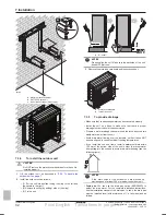
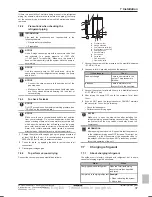
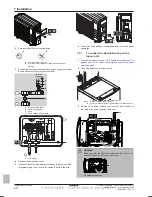
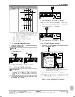
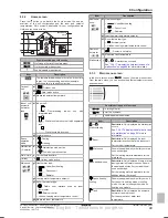
Strip insulation (20 mm) from the wires.
a
b
a
Strip wire end to this point
b
Excessive strip length may cause electrical shock or
leakage.
3
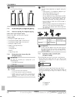
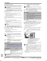
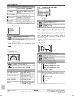
Connect the interconnection cable and power supply as follows.
Ensure stress relief by using the wire clamp.
a
c
d
1N~ 50 Hz
220-240 V
b
a
Interconnection cable
b
Power supply cable
c
Fuse
d
Earth leakage circuit breaker
1 2 3
L
N
L N PWR
12 3
3×
a
a
Wire clamp
4
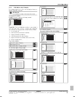
Reattach the switch box cover.
5
Optional: Attach the wire clamp (accessory) to the screw of the
refrigerant piping cover, and fix the cables to it with a cable tie.
1×
1×
6
Connect an earth leakage circuit breaker and fuse to the power
supply line.
7.9.7
To connect the electrical wiring on the
indoor unit
1
To open the indoor unit, see
"7.2.3 To open the indoor unit" on
page 29
and
"7.2.4 To open the switch box cover of the indoor
unit" on page 30
.
2
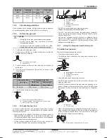
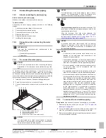
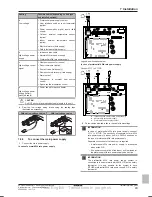
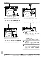
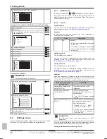
The wiring enters the unit from the top:
b+c
a
d
a, b, c
Field wiring (see table below)
d
Factory-mounted cable for power supply of backup heater
3
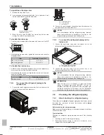
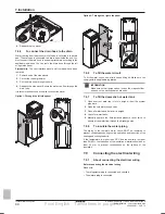
Routing of the wiring inside the unit should be as follows. Fix
the cable to the cable rail using cable ties:
a
4×
b+c
WARNING
Make sure that the electrical wiring does NOT touch the
refrigerant gas pipe, which can be very hot.
a
a
Refrigerant gas pipe
Final English - Tanslations in progress

