6 Preparation
Installer reference guide
27
ERGA04~08DAV3(A) + EHVH/X04+08S18+23DA
Daikin Altherma – Low temperature split
4P495248-1 – 2017.12
h
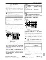
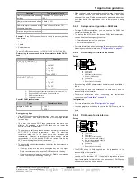
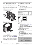
Overpressure bypass valve (delivered as accessory)
FHL1...3
Floor heating loop (field supply)
T1...3
Individual room thermostat (optional)
M1...3
Individual motorised valve to control loop FHL1...3 (field
supply)
Maximum water volume
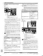
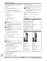
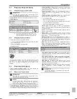
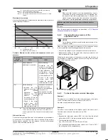
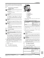
Use the following graph to determine the maximum water volume for
the calculated pre-pressure.
0.3
0.5
1
1.5
2
2.4
50
20
100
150
200
250
290
a
b
a
Pre-pressure (bar)
b
Maximum water volume (l)
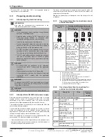
Example: Maximum water volume and expansion vessel pre-
pressure
Installation
height
difference
(a)
Water volume
≤200 l
>200 l
≤7 m
No pre-pressure
adjustment is required.
Do the following:
▪ Decrease
the
pre-
pressure according to
the required installation
height difference. The
pre-pressure
should
decrease by 0.1 bar for
each metre below 7 m.
▪ Check if the water
volume
does
NOT
exceed the maximum
allowed water volume.
>7 m
Do the following:
▪ Increase
the
pre-
pressure according to
the
required
installation
height
difference. The pre-
pressure
should
increase by 0.1 bar for
each metre above 7 m.
▪ Check if the water
volume
does
NOT
exceed the maximum
allowed water volume.
The expansion vessel of
the indoor unit is too
small for the installation.
In this case, it is
recommended to install
an extra vessel outside
the unit.
(a)
This is the height difference (m) between the highest point
of the water circuit and the indoor unit. If the indoor unit is
at the highest point of the installation, the installation height
is 0 m.
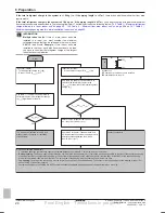
Minimum flow rate
Check that the minimum flow rate in the installation is guaranteed in
all conditions. This minimum flow rate is required during defrost/
backup heater operation. For this purpose, use the overpressure
bypass valve delivered with the unit.
NOTICE
When circulation in each or certain space heating loops is
controlled by remotely controlled valves, it is important that
the minimum flow rate is guaranteed, even if all valves are
closed. In case the minimum flow rate cannot be reached,
a flow error 7H will be generated (no heating or operation).
Minimum required flow rate during defrost/backup heater
operation
12 l/min
See the recommended procedure as described in
"9.4 Checklist
during commissioning" on page 77
.
6.4.4
Changing the pre-pressure of the
expansion vessel
NOTICE
Only a licensed installer may adjust the pre-pressure of the
expansion vessel.
When changing the default pre-pressure of the expansion vessel
(1 bar) is required, take following guidelines into account:
▪ Only use dry nitrogen to set the expansion vessel pre-pressure.
▪ Inappropriate setting of the expansion vessel pre-pressure will
lead to malfunction of the system.
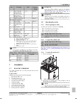
Changing the pre-pressure of the expansion vessel should be done
by releasing or increasing nitrogen pressure through the Schrader
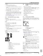
valve of the expansion vessel.
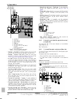
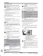
a
a
Schrader valve
6.4.5
To check the water volume: Examples
Example 1
The indoor unit is installed 5 m below the highest point in the water
circuit. The total water volume in the water circuit is 100 l.
No actions or adjustments are required.
Example 2
The indoor unit is installed at the highest point in the water circuit.
The total water volume in the water circuit is 250 l.
Actions:
▪ Because the total water volume (250 l) is more than the default
water volume (200 l), the pre-pressure must be decreased.
▪ The required pre-pressure is:
Pg = (0.3+(H/10)) bar = (0.3+(0/10)) bar=0.3 bar.
▪ The corresponding maximum water volume at 0.3 bar is 290 l.
(See the graph in the chapter above).
Final English - Tanslations in progress

