


Si18-525B
Instruction
Operation Manual
205
Outdoor Unit
Indoor Unit
1. Air filter
2. Air purifying filter with photocatalytie
deodorizing function:
• These filters are attached to the inside of the air
filters.
3. Air inlet
4. Front grille
5. Grille tab
6. INTELLIGENT EYE sensor:
• It detects the movements of people and
automatically switches between normal operation
and energy saving operation.
7. Display
8. Air outlet
9. Flap (horizontal blade)
10. Louvers (vertical blades):
• The Louvers are inside of the air outlet.
11. Operation lamp (green)
12. TIMER lamp (yellow)
13. HOME LEAVE lamp (red):
• Lights up when you use HOME LEAVE
Operation.
14. Indoor Unit ON/OFF switch:
• Push this switch once to start operation.
Push once again to stop it.
• The operation mode refer to the following table.
• This switch is useful when the remote controller
is missing.
15. Packaging materials: 50 class only
• If any packaging materials are included,
please remove before operating.
16. Room temperature sensor:
• It senses the air temperature around the unit.
17. Signal receiver:
It receives signals from the remote controller.
When the unit receives a signal, you will hear a
short beep.
• Operation start .............beep-beep
• Settings changed ..........beep
• Operation stop ..............beeeeep
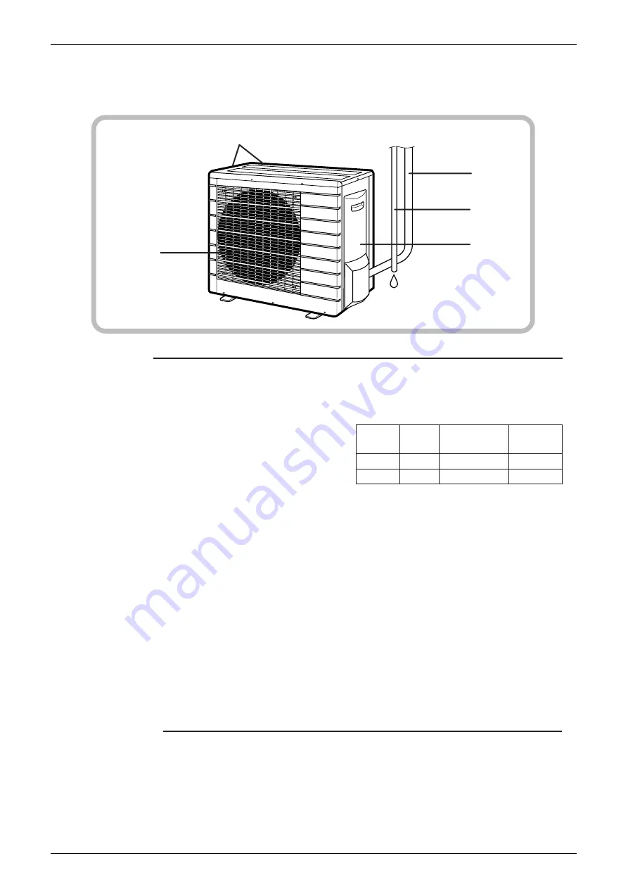
Outdoor Unit
18. Air inlet: (Back and side)
19. Air outlet
20. Refrigerant piping and inter-unit cable
21. Drain hose
22. Earth terminal:
• It is inside of this cover.
Appearance of the outdoor unit may differ from some models.
20
21
22
19
18
Mode
Temperature
setting
Air flow
rate
FTKS
COOL
22
°
C
AUTO
FTXS
AUTO
25
°
C
AUTO
Содержание D-Series
Страница 1: ...Si18 525B Applied Models Super Multi Plus Cooling only Super Multi Plus Heat Pump D Series ...
Страница 33: ...List of Functions Si18 525B 20 List of Functions ...
Страница 34: ...Si18 525B Specifications 21 Part 2 Specifications 1 Specifications 22 1 1 Cooling Only 22 1 2 Heat Pump 42 ...
Страница 71: ...Specifications Si18 525B 58 Specifications ...
Страница 107: ...Printed Circuit Board Connector Wiring Diagram Si18 525B 94 Printed Circuit Board Connector Wiring Diagram ...
Страница 117: ...Refrigerant Flow for Each Operation Mode Si18 525B 104 Refrigerant Circuit ...
Страница 171: ...Indoor Unit SkyAir Models Si18 525B 158 Function ...
Страница 207: ...Test Operation and Field Setting for RA Indoor Unit Si18 525B 194 Test Operation ...
Страница 336: ...Si18 525B Service Check Function Troubleshooting 323 ...
Страница 443: ...BP Unit Si18 525B 430 Removal Procedure The clamps are to be kept in stock Step Procedure Points Clamps Q0529 ...
Страница 469: ...Wiring Diagrams Si18 525B 456 Appendix ...
Страница 475: ...Si18 525B vi Index ...


