


Test Operation
Si18-525B
162
Test Operation
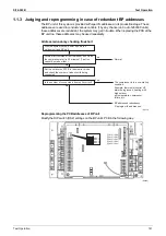
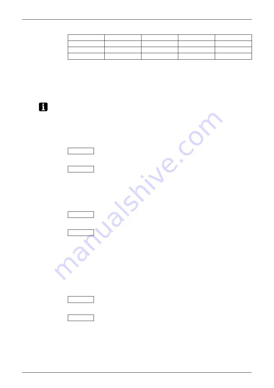
Example of DIP switch (DS2) settings on the BP unit's PCB
DS1~4 : Factory setting is OFF.
The BP unit 1 through 3 show the first through third unit, respectively. The order of these units is
flexible.
The above table is just for your reference. The redundancy of addresses can be avoided when
the DIP switch settings are individually specified.
With the DIP switch settings reprogrammed, power on the outdoor unit and BP unit again.
Check for address redundancy.
Note:
If an error display appears on the indoor unit, BP unit or outdoor unit, follow its code and
description.
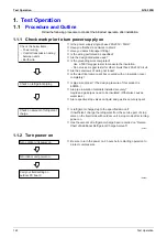
1.1.4
When Turning On Power First Time
The unit cannot be run for up to 12 minutes to automatically set address (indoor-outdoor
address, etc.).
Status
1.1.5 When Turning On Power the Second Time and Subsequent
Tap the RESET(BS5) button on the outdoor unit PCB. Operation becomes possible for about 2
minutes. If not, the unit cannot be run for up to 10 minutes.
Status
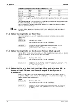
1.1.6 When the No. of Indoor Unit Has Been Changed, or Indoor (BP) or
Outdoor Unit PC Board Has Been Changed, or the System is
transferred
Be sure to push and hold the RESET button for 5 seconds. If not, the addition cannot be
recognized. In this case, the unit cannot be run for up to 12 minutes to automatically set the
address (indoor-outdoor address, etc.)
Status
DS2-1
DS2-2
DS2-3
DS2-4
BP unit 1
OFF
OFF
ON
OFF
BP unit 2
OFF
OFF
OFF
ON
BP unit 3
OFF
OFF
ON
ON
Outdoor unit
Test lamp H2P .... Blinks
Can also be set during operation described above.
Indoor unit
If ON button is pushed during operation described above, the “UH”
malfunction indicator blinks.
(Returns to normal when automatic setting is complete.)
Outdoor unit
Test lamp H2P .... Blinks
Can also be set during operation described above.
Indoor unit
If ON button is pushed during operation described above, the operation lamp
lights but the compressor does not operate. (Returns to normal when
automatic setting is complete.)
Outdoor unit
Test lamp H2P .... ON
Can also be set during operation described above.
Indoor unit
If ON button is pushed during operation described above, the “UH” or “U4”
malfunction indicator blinks. (Returns to normal when automatic setting is
complete.)
Содержание D-Series
Страница 1: ...Si18 525B Applied Models Super Multi Plus Cooling only Super Multi Plus Heat Pump D Series ...
Страница 33: ...List of Functions Si18 525B 20 List of Functions ...
Страница 34: ...Si18 525B Specifications 21 Part 2 Specifications 1 Specifications 22 1 1 Cooling Only 22 1 2 Heat Pump 42 ...
Страница 71: ...Specifications Si18 525B 58 Specifications ...
Страница 107: ...Printed Circuit Board Connector Wiring Diagram Si18 525B 94 Printed Circuit Board Connector Wiring Diagram ...
Страница 117: ...Refrigerant Flow for Each Operation Mode Si18 525B 104 Refrigerant Circuit ...
Страница 171: ...Indoor Unit SkyAir Models Si18 525B 158 Function ...
Страница 207: ...Test Operation and Field Setting for RA Indoor Unit Si18 525B 194 Test Operation ...
Страница 336: ...Si18 525B Service Check Function Troubleshooting 323 ...
Страница 443: ...BP Unit Si18 525B 430 Removal Procedure The clamps are to be kept in stock Step Procedure Points Clamps Q0529 ...
Страница 469: ...Wiring Diagrams Si18 525B 456 Appendix ...
Страница 475: ...Si18 525B vi Index ...


