


Special Control
Si18-525B
114
Function
3.
Special Control
3.1
Startup Control
On activation, following control is performed to lighten load of the compressor by back liquid and
the like. Also, the position of the four way valve is defined.
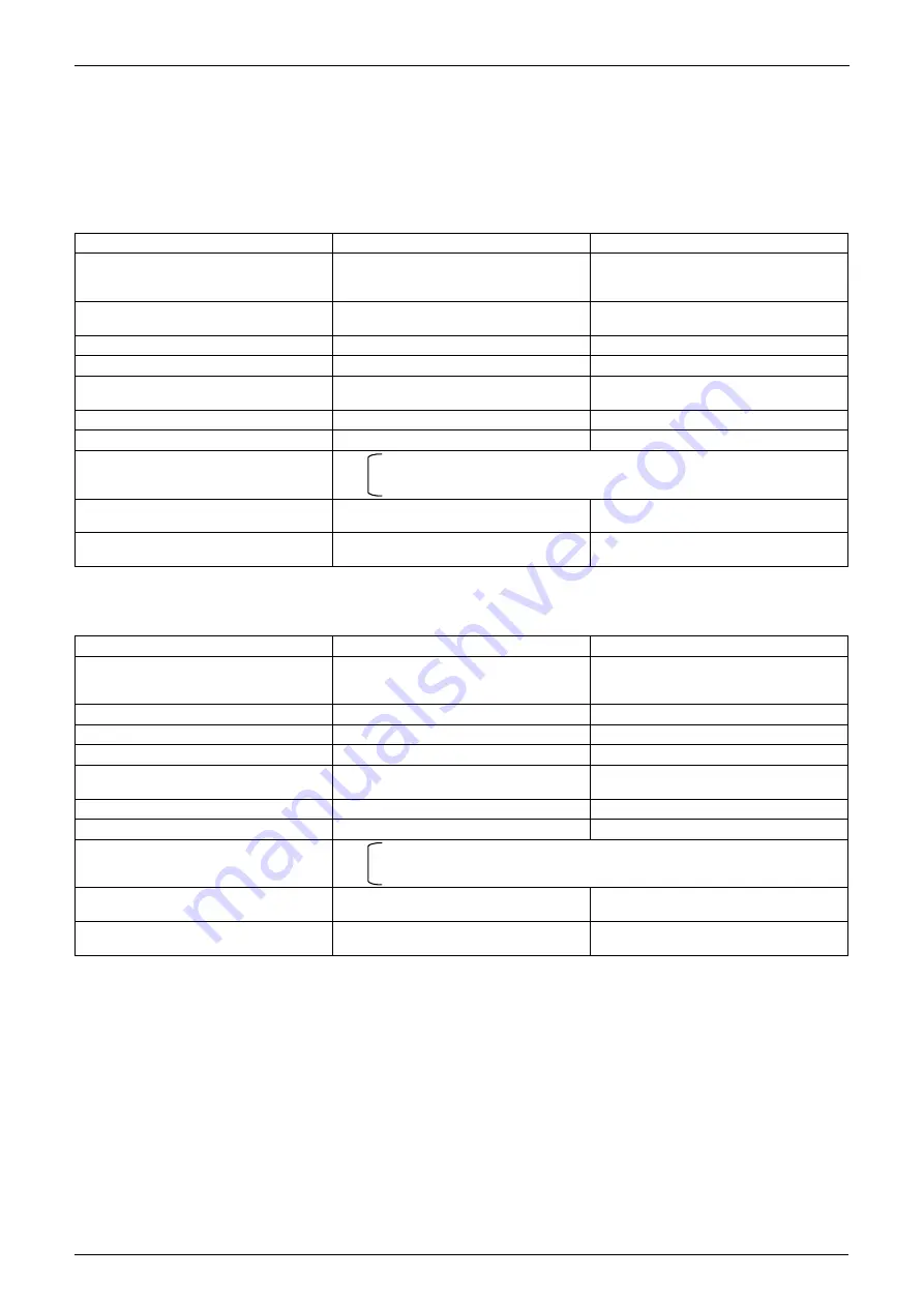
3.1.1 Startup Control in Cooling Operation
3.1.2 Startup Control in Heating Operation
Actuator
Operation
Remarks
Compressor
Differential pressure control
Compressor operating frequency
increases by 2 step / 20 sec until
Pc - Pe>0.4 MPa.
Outdoor unit fan
High pressure control
Initial fan speed is set to STEP 0
(Ta
<
20°C), or STEP 7 (Ta
≥
).
Four way valve
OFF
Main electronic expansion valve (EV1)
2000 pls
Subcooling electronic expansion valve
(EV2)
0 pls
Hot gas bypass valve (SVP)
ON
Receiver gas discharging valve (SVG)
OFF
Ending conditions
•
255 sec.
•
Pc - Pe>0.4 MPa
•
75 sec
BP unit electronic expansion valve
(operating room)
0 pls
BP unit electronic expansion valve
(stopping room)
0 pls
Actuator
Operation
Remarks
Compressor
Differential pressure control
Compressor operating frequency
increases by 2 step / 20 sec until
Pc - Pe>0.4 MPa.
Outdoor unit fan
STEP8
Four way valve
ON
Main electronic expansion valve (EV1)
180 pls
Subcooling electronic expansion valve
(EV2)
0 pls
Hot gas bypass valve (SVP)
ON
Receiver gas discharging valve (SVG)
ON
Ending conditions
•
225 sec.
•
Pc - Pe>0.4 MPa
•
40 sec
BP unit electronic expansion valve
(operating room)
0 pls
BP unit electronic expansion valve
(stopping room)
0 pls
or
&
(
or
&
(
Содержание D-Series
Страница 1: ...Si18 525B Applied Models Super Multi Plus Cooling only Super Multi Plus Heat Pump D Series ...
Страница 33: ...List of Functions Si18 525B 20 List of Functions ...
Страница 34: ...Si18 525B Specifications 21 Part 2 Specifications 1 Specifications 22 1 1 Cooling Only 22 1 2 Heat Pump 42 ...
Страница 71: ...Specifications Si18 525B 58 Specifications ...
Страница 107: ...Printed Circuit Board Connector Wiring Diagram Si18 525B 94 Printed Circuit Board Connector Wiring Diagram ...
Страница 117: ...Refrigerant Flow for Each Operation Mode Si18 525B 104 Refrigerant Circuit ...
Страница 171: ...Indoor Unit SkyAir Models Si18 525B 158 Function ...
Страница 207: ...Test Operation and Field Setting for RA Indoor Unit Si18 525B 194 Test Operation ...
Страница 336: ...Si18 525B Service Check Function Troubleshooting 323 ...
Страница 443: ...BP Unit Si18 525B 430 Removal Procedure The clamps are to be kept in stock Step Procedure Points Clamps Q0529 ...
Страница 469: ...Wiring Diagrams Si18 525B 456 Appendix ...
Страница 475: ...Si18 525B vi Index ...


