ENGLISH
70
GB
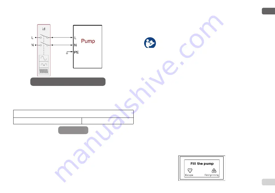
Figure 11 - bis Installation example
The thermal magnetic circuit breaker must be correctly sized (see Electri-
The thermal magnetic circuit breaker must be correctly sized (see Electri-
cal Characteristics).
cal Characteristics).
The appliance must be connected to a main switch that cuts off all the
The appliance must be connected to a main switch that cuts off all the
power supply poles. When the switch is in off position, the distance sepa-
power supply poles. When the switch is in off position, the distance sepa-
rating each contact must respect the indications in table 1b.
rating each contact must respect the indications in table 1b.
Minimum distance between the contacts of the power switch
Minimum distance [mm]
>3
3.2 Configuration of the Integrated Inverter
3.2 Configuration of the Integrated Inverter
The system is configured by the manufacturer to satisfy the majority of
The system is configured by the manufacturer to satisfy the majority of
installation cases, that is:
installation cases, that is:
•
•
operation at constant pressure;
operation at constant pressure;
•
•
Set-Point (desired value of constant pressure):
SP = 3.0 bar
Set-Point (desired value of constant pressure):
SP = 3.0 bar
•
•
Reduction of pressure to restart:
RP = 0.3 bar
Reduction of pressure to restart:
RP = 0.3 bar
•
•
Anti-cycling function:
Disabled
Anti-cycling function:
Disabled
However, all these parameters and many others can be set by the user.
However, all these parameters and many others can be set by the user.
Table 1b
There are many other operating modes and accessory functions. Thanks
There are many other operating modes and accessory functions. Thanks
to the different possible settings and the availability of configurable input
to the different possible settings and the availability of configurable input
and output channels, it is possible to adapt the inverter operation to the
and output channels, it is possible to adapt the inverter operation to the
requirements of various systems. See par. 5-6-7
requirements of various systems. See par. 5-6-7
For the definition of the parameters SP and RP, the pressure at
For the definition of the parameters SP and RP, the pressure at
which the system starts has the value:
which the system starts has the value:
Pstart = SP – RP
Pstart = SP – RP
For example: 3.0 – 0.3 = 2.7 bar
For example: 3.0 – 0.3 = 2.7 bar
in the default configuration
in the default configuration
The system does not work if the utility is at a height higher than the equiv
-
The system does not work if the utility is at a height higher than the equiv
-
alent in metres of water column of the Pstart (consider 1 bar = 10 m water
alent in metres of water column of the Pstart (consider 1 bar = 10 m water
column): for the default configuration, if the utility is at a height of at least
column): for the default configuration, if the utility is at a height of at least
27m the system does not start.
27m the system does not start.
3.3 - Priming
3.3 - Priming
The priming of a pump is the phase during which the machine attempts to
The priming of a pump is the phase during which the machine attempts to
fill the body and the suction pipe with water. If the operation is successful
fill the body and the suction pipe with water. If the operation is successful
the machine can work regularly.
the machine can work regularly.
Once the pump has been filled (par. 2.1.2, 2.2.3) and the device has been
Once the pump has been filled (par. 2.1.2, 2.2.3) and the device has been
configured (par. 3.2), it is possible to connect the electric power supply
configured (par. 3.2), it is possible to connect the electric power supply
after having opened at least one utility on delivery.
after having opened at least one utility on delivery.
The system starts and checks the presence of water in delivery for the first
The system starts and checks the presence of water in delivery for the first
10 seconds.
10 seconds.
If a flow of water is detected in delivery, the pump is primed and starts its
If a flow of water is detected in delivery, the pump is primed and starts its
regular work. This is the typical case of installation below head (par. 2.1.2,
regular work. This is the typical case of installation below head (par. 2.1.2,
2.2.3). The utility opened in delivery from which the pumped water is com
-
2.2.3). The utility opened in delivery from which the pumped water is com
-
ing out can be closed.
ing out can be closed.
If a regular flow in delivery is not detected after 10 seconds, the system
If a regular flow in delivery is not detected after 10 seconds, the system
asks for confirmation to enter the priming procedure (typical case of instal
-
asks for confirmation to enter the priming procedure (typical case of instal
-
lation above head par. 2.1.2, 2.2.3).
lation above head par. 2.1.2, 2.2.3).
Or:
Or:
Содержание e.sybox Series
Страница 3: ......


