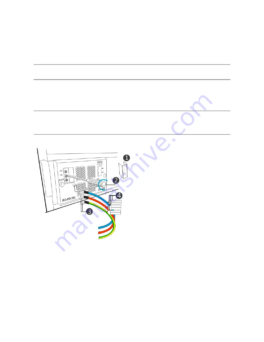
The RG-PD1200 and RG-PD2000 are installed in a similar way. The following procedure describes how to install the
RG-PD1200, as shown in Figure 3-29:
1)
Take out the RG-PD1200 and DC power cable from the packing case. Install the RG-PD1200 into the power slot in
the chassis.
2)
With a screwdriver, remove the insulating cover from the DC wiring terminal
and loosen the screw as indicated in
.
3)
Connect the DC power cable terminals to the wiring terminals
③
of the power supply, and tighten the screws.
Connect the red DC power wire to the power supply’s positive pole, specifically the RTN wiring terminal (the middle
binding post), the blue one to the negative pole namely the -48 V wiring terminal (the top binding post), and the
yellow-green grounding cable to the third wiring terminal (the bottom binding post).
4)
Put on the insulating cover and tighten the screw.
5)
Bundle the power cables with a cable tie to the rack. Tie a label
④
to each power cable to mark the type of the
related power module.
6)
Connect the other ends of the DC power cables to the distribution panel with the red one to the RTN terminal, the
blue one to the -48 V terminal, and the yellow-green grounding cable to the PGND terminal.
To tell apart positive and negative terminals, set the multimeter to DC position and use the red and black probes to
measure the two wiring terminals. If the multimeter shows positive voltage, the black probe points to the negative
terminal, which should be connected to the blue power cable. The terminal at the red probe should be connected to
the red cable. If negative voltage is shown, connect the terminal at the black probe to the red power cable and the
other terminal to the blue one.
Figure 3-30 Installing RG-PD1200 V2.00 or Earlier
Содержание RG-S8606 B
Страница 1: ...RG S8600 Series Switch Hardware Installation and Reference Guide V1 78 ...
Страница 58: ...Figure 2 3 Moving the RG S8606 Switch Figure 2 4 Moving the RG S8606 B Switch ...
Страница 62: ...Figure 2 6 Ventilation of RG S8614 ...
Страница 63: ...Figure 2 7 Ventilation of RG S8610 Figure 2 8 Ventilation of RG S8606 ...
Страница 76: ...Figure 3 8 Installing the Power Supply of the RG S8606 Switch ...
Страница 92: ...Figure 3 34 Board Components of the RG S8610 Figure 3 35 Board Components of RG S8606 ...
Страница 116: ......


