background image

DWS-3160 Series Gigabit Ethernet Unified Switch Web UI Reference Guide 

343 


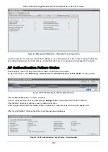
Figure 2-12 All AP Status window 


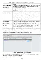
The fields that can be displayed are described below: 

Parameter 

Description 

MAC Address 

Display the MAC address of the access point. 

Location 

A location description for the AP. This is the value configured in the valid AP 
database (either locally or on the RADIUS server). 

Switch Port 

The physical port (in the slot/port format) on the switch that the AP is connected to 
either directly or indirectly in the same L3 domain. If the AP is beyond the L3 
network boundary, then ‘Unknown’ is displayed. 

IP Address 

The network address of the access point. 

Software Version 

Display the version of D-Link Access Point software that the AP is running. 

Age 

Display how much time has passed since the AP was last detected and the 
information was last updated. 

Status 

Display the access point status. 


Managed

 - The AP profile configuration has been applied to the AP and it's 

operating in managed mode. 


No Database Entry

 - The MAC address of the AP does not appear in the local 

or RADIUS Valid AP database. 


Authentication (Failed AP)

 - The AP failed to be authenticated by the Unified 

Switch or RADIUS server. 


Failed

 - The Unified Switch lost contact with the AP; a failed entry will remain in 

the managed AP database unless you remove it. Note that a managed AP will 
temporarily show a failed status during a reset. 


Rogue

 - The AP has not attempted to contact the switch, and the MAC address 

of the AP is not in the Valid AP database. 

Profile 

The AP profile configuration currently applied to the managed AP. The profile is 
assigned to the AP in the valid AP database. 

NOTE:

 Once an AP is discovered and managed by the Unified Switch, if the profile 

is changed in the valid AP database (either locally or on the RADIUS 
server) the AP is automatically reset when a new profile is assigned. 

Radio 

Display the wireless radio mode the AP is using. 

Channel 

Display the operating channel for the radio. 

Authenticated Clients 

Display the number of wireless clients that are associated and authenticated with 
the access point per radio. 

Click the 

Delete All

 button to remove all entries from the list except Managed Access Points. 

Tick the corresponding check box and click the 

Manage

 button to configure an Authentication Failed AP to be 

managed by the Switch the next time it is discovered. 

Tick the corresponding check box and click the 

Acknowledge

 button to identify an AP as an Acknowledged Rogue.  

Enter a page number and click the 

Go

 button to navigate to a specific page when multiple pages exist. 


Содержание DWS-3160-24TC

Страница 1: ...Fdo...

Страница 2: ...Corporation is strictly forbidden Trademarks used in this text D Link and the D LINK logo are trademarks of D Link Corporation Microsoft and Windows are registered trademarks of Microsoft Corporation...

Страница 3: ...ettings 7 Port Configuration 7 PoE 11 Serial Port Settings 14 Warning Temperature Settings 14 System Log Configuration 15 Time Range Settings 18 Port Group Settings 19 Time Settings 19 User Accounts S...

Страница 4: ...st 179 Egress ACL Flow Meter 191 Chapter 7 Security 194 802 1X 194 RADIUS 206 IP MAC Port Binding IMPB 210 MAC based Access Control MAC 215 Compound Authentication 218 Port Security 221 ARP Spoofing P...

Страница 5: ...Download Image 457 Launch 457 Section 4 Save and Tools 460 Chapter 1 Save 460 Save Configuration Log 460 Chapter 2 Tools 461 License Management 461 Download Firmware 461 Upload Firmware 462 Download...

Страница 6: ...le menu and choose Cancel Used for emphasis May also indicate system messages or prompts appearing on screen For example You have mail Bold font is also used to represent filenames program names and c...

Страница 7: ...tch using the HTTP protocol The Web based management module and the Console program and Telnet are different ways to access the same internal switching software and configure it Thus all settings enco...

Страница 8: ...management features available in the web based manager are explained below Chapter 3 Web based User Interface The user interface provides access to various Switch configuration and management windows...

Страница 9: ...activity Click the D Link logo to go to the D Link website Some management functions including save reboot download and upload are accessible here Area 3 Presents switch information based on user sele...

Страница 10: ...onfigure features regarding the Switch s operations administration and maintenance OAM Monitoring In this section the user will be able to monitor the Switch s configuration and statistics WLAN Tab Se...

Страница 11: ...rn to the Device Information window after viewing other windows click the DWS 3160 Series link The Device Information window shows the Switch s MAC Address assigned by the factory and unchangeable the...

Страница 12: ...ds that can be configured are described below Parameter Description System Name Enter a system name for the Switch if so desired This name will identify it in the Switch network System Location Enter...

Страница 13: ...ttings The other options are 10M Half 10M Full 100M Half 100M Full 1000M Full_Master 1000M Full_Slave and 1000M Full There is no automatic adjustment of port settings with any option other than Auto T...

Страница 14: ...or efficiency See the section on Forwarding Filtering for information on entering MAC addresses into the forwarding table The default setting is Enabled MDIX Auto Select auto for auto sensing of the...

Страница 15: ...bed below Parameter Description Port Display the port that has been error disabled Port State Describe the current running state of the port whether enabled or disabled Connection Status Display the u...

Страница 16: ...er consumption exceeds the per port power limit Active circuit protection automatically disables the port if there is a short Other ports will remain active Based on 802 3af at PDs receive power accor...

Страница 17: ...Disconnect Method is Deny Next Port Both Power Disconnection Methods are described below Deny Next Port After the power limit has been exceeded the next port attempting to power up is denied regardle...

Страница 18: ...to have the same level of priority the port ID will be used to determine the priority The lower port ID has higher priority The setting of priority will affect the order of supplying power Whether th...

Страница 19: ...Select the logout time used for the console interface This automatically logs the user out after an idle period of time as defined Choose from the following options 2 5 10 15 minutes or Never The defa...

Страница 20: ...tings Save Mode Use the drop down menu to choose the method for saving the switch log to the flash memory The user has three options On Demand Users who choose this method will only save log files whe...

Страница 21: ...he drop down menu to select Local 0 Local 1 Local 2 Local 3 Local 4 Local 5 Local 6 or Local 7 UDP Port 514 or 6000 65535 Type the UDP port number used for sending Syslog messages The default is 514 S...

Страница 22: ...Clear Log button to clear the entries from the log in the display section Click the Clear Attack Log button to clear the entries from the attack log in the display section The Switch can record event...

Страница 23: ...ke an effect on such as ACL For example the administrator can configure the time based ACL to allow users to surf the Internet on every Saturday and every Sunday meanwhile to deny users to surf the In...

Страница 24: ...The fields that can be configured are described below Parameter Description Group Name Enter the name of a port group Group ID 1 64 Enter the ID of a port group Port List Enter a port or list of ports...

Страница 25: ...Configuration Files Read Write Read Write No No System Utilities Read Write Read only Read only Read only Factory Reset Read Write No No No User Account Management Add Update Delete User Accounts Read...

Страница 26: ...ing Settings window The fields that can be configured are described below Parameter Description Command Logging State Use the radio buttons to enable or disable the function Click the Apply button to...

Страница 27: ...s as show below Figure 6 1 Static ARP Settings window The fields that can be configured are described below Parameter Description ARP Aging Time 0 65535 The ARP entry age out time in minutes The defau...

Страница 28: ...dit button to re configure the specific entry and select the proxy ARP state of the IP interface By default both the Proxy ARP State and Local Proxy ARP State are disabled ARP Table Users can display...

Страница 29: ...t packet that is sent by an IP address that match the system s own IP address In this case the system knows that somebody out there uses an IP address that is conflict with the system In order to recl...

Страница 30: ...the Layer 3 interface Select All to enable or disable gratuitous ARP trap or log on all interfaces Interval Time 0 65535 Enter the periodically send gratuitous ARP interval time in seconds 0 means tha...

Страница 31: ...ess Static or Dynamic When the user selects address from the drop down menu the user will be able to enter an IP address in the space provided next to the state option Click the Add button to add a ne...

Страница 32: ...describe the fields that are about the System Interface Parameter Description Interface Name Display the System interface name Management VLAN Name This allows the entry of a VLAN name from which a ma...

Страница 33: ...nter the name of the IP interface to search for Click the Find button to locate a specific entry based on the information entered Click the Add button to add a new entry based on the information enter...

Страница 34: ...tings Edit window The fields that can be configured are described below Parameter Description Get IP From Use the drop down menu to specify the method that this Interface uses to acquire an IP address...

Страница 35: ...limits of the console when using the Command Line Interface This window is also used to enable the DHCP auto configuration feature on the Switch When enabled the Switch is instructed to receive a con...

Страница 36: ...ed in its base directory when the request is received from the Switch Power Saving State Enable or disable the link down power saving mode of each physical port The switch port will go into sleep mode...

Страница 37: ...p cannot cross a router There is no limit to the number of SIM groups in the same IP subnet broadcast domain however a single switch can only belong to one group If multiple VLANs are configured the S...

Страница 38: ...cover member switches that have left the SIM group either through a reboot or web malfunction This feature is accomplished through the use of Discover packets and Maintenance packets that previously s...

Страница 39: ...to segment switches into different SIM groups Discovery Interval 30 90 The user may set the discovery protocol interval in seconds that the Switch will send out discovery packets Returning information...

Страница 40: ...isplays the number of the physical port on the CS that the MS or CaS is connected to The CS will have no entry in this field Speed Displays the connection speed between the CS and the MS or CaS Remote...

Страница 41: ...2 commander switch Member switch of other group Layer 3 commander switch Layer 2 candidate switch Commander switch of other group Layer 3 candidate switch Layer 2 member switch Unknown device Non SIM...

Страница 42: ...e cursor over a line between two devices will display the connection speed between the two devices as shown below Figure 6 19 Port Speed Utilizing the Tool Tip Right clicking on a device will allow th...

Страница 43: ...evice Name is configured by the name it will be given the name default and tagged with the last six digits of the MAC Address to identify it Module Name Displays the full module name of the switch tha...

Страница 44: ...To expand the SIM group in detail Remove from group Remove a member from a group Configure Launch the web management to configure the Switch Property To pop up a window to display the device informati...

Страница 45: ...password or Cancel to exit the dialog box Group Figure 6 27 Input password window Remove from Group Remove an MS from the group Configure Will open the Web manager for the specific device Device Refre...

Страница 46: ...File The following window is used to upload log files from SIM member switches to a specified PC To upload a log file enter the Server IP address of the SIM member switch and then enter a Path Filenam...

Страница 47: ...r OID associated with a specific MIB An additional layer of security is available for SNMPv3 in that SNMP messages may be encrypted To read more about how to configure SNMPv3 settings for the Switch r...

Страница 48: ...ettings SNMP Traps Settings as show below Figure 6 33 SNMP Traps Settings window The fields that can be configured are described below Parameter Description SNMP Traps Enable this option to use the SN...

Страница 49: ...nge Trap Click the Apply button to accept the changes made SNMP View Table Settings Users can assign views to community strings that define which MIB objects can be accessed by a remote SNMP manager T...

Страница 50: ...ccess to the Switch s SNMP agent Any MIB view that defines the subset of all MIB objects will be accessible to the SNMP community Read write or read only level permission for the MIB objects accessibl...

Страница 51: ...pecify that SNMP version 1 will be used SNMPv2 Specify that SNMP version 2c will be used The SNMPv2 supports both centralized and distributed network management strategies It includes improvements in...

Страница 52: ...y button to accept the changes made NOTE The Engine ID length is 10 64 and accepted characters can range from 0 to F SNMP User Table Settings This window displays all of the SNMP User s currently conf...

Страница 53: ...To view the following window click Management SNMP Settings SNMP Host Table Settings as show below Figure 6 40 SNMP Host Table Settings window The fields that can be configured are described below Par...

Страница 54: ...a NoAuth NoPriv security level AuthNoPriv To specify that the SNMP version 3 will be used with an Auth NoPriv security level AuthPriv To specify that the SNMP version 3 will be used with an Auth Priv...

Страница 55: ...65535 The TCP port number used for Telnet management of the Switch The well known TCP port for the Telnet protocol is 23 Click the Apply button to accept the changes made Web Settings Users can config...

Страница 56: ...ailor how priority tagged data packets are handled on your network Using queues to manage priority tagged data allows you to specify its relative priority to suit the needs of your network There may b...

Страница 57: ...of the packet header Ingress port A port on a switch where packets are flowing into the Switch and VLAN decisions must be made Egress port A port on a switch where packets are flowing out of the Swit...

Страница 58: ...ce is indicated by a value of 0x8100 in the EtherType field When a packet s EtherType field is equal to 0x8100 the packet carries the IEEE 802 1Q 802 1p tag The tag is contained in the following two o...

Страница 59: ...e defined on the Switch all ports are then assigned to a default VLAN with a PVID equal to 1 Untagged packets are assigned the PVID of the port on which they were received Forwarding decisions are bas...

Страница 60: ...mits it to its attached network segment If the packet is not tagged with VLAN information the ingress port will tag the packet with its own PVID as a VID if the port is a tagging port The switch then...

Страница 61: ...kets If Port 10 is not a member of VLAN 2 then the packet will be dropped by the Switch and will not reach its destination If Port 10 is a member of VLAN 2 the packet will go through This selective fo...

Страница 62: ...t to configure Port Display all ports of the Switch for the configuration option Tagged Specify the port as 802 1Q tagging Clicking the radio button will designate the port as tagged Click the All but...

Страница 63: ...on VID List Enter a VLAN ID List that can be added deleted or configured Advertisement Enabling this function will allow the Switch to send out GVRP packets to outside sources notifying that they may...

Страница 64: ...ic string of up to 32 characters Protocol This function maps packets to protocol defined VLANs by examining the type octet within the packet header to discover the type of protocol associated with it...

Страница 65: ...that match this priority are forwarded to the CoS queue specified previously by the user Click the corresponding box if you want to set the 802 1p default priority of a packet to the value entered in...

Страница 66: ...distinct IP subnet or if there was some confidentiality related need to segregate traffic between the clients To view this window click L2 Features VLAN Asymmetric VLAN Settings as show below Figure...

Страница 67: ...VRP GVRP Port Settings as show below Figure 7 12 GVRP Port Settings window The fields that can be configured are described below Parameter Description From Port To Port Select the starting and ending...

Страница 68: ...dress VID 1 4094 Select this option and enter the VLAN ID VLAN Name Select this option and enter the VLAN name of a previously configured VLAN Click the Find button to locate a specific entry based on...

Страница 69: ...elow Parameter Description VLAN Name Enter a VLAN name VID 2 4094 Enter a VID value VLAN List Enter a list of VLAN IDs Click the Add button to add a new entry based on the information entered Click th...

Страница 70: ...Global Settings Voice VLAN is a VLAN used to carry voice traffic from IP phone Because the sound quality of an IP phone call will be deteriorated if the data is unevenly sent the quality of service Qo...

Страница 71: ...of voice VLAN aging timer If the voice traffic resumes during the aging time the aging timer will be reset and stop Log State Used to enable disable sending of issue of voice VLAN log Click the Apply...

Страница 72: ...evice This page is used to show voice devices that are connected to the ports The start time is the time when the device is detected on this port the activate time is the latest time saw the device se...

Страница 73: ...Parameter Description VLAN Trunk State Enable or disable the VLAN trunking global state Ports The ports to be configured By clicking the Select All button all the ports will be included By clicking th...

Страница 74: ...This basically lets large ISP s create L2 Virtual Private Networks and also create transparent LANs for their customers which will connect two or more customer LAN points without over complicating co...

Страница 75: ...th the implementation of the Double VLAN procedure Regulations for Double VLANs 1 All ports must be configured for the SPVID and its corresponding TPID on the Service Provider s edge switch 2 All port...

Страница 76: ...or NNI port Missdrop This option enables or disables C VLAN based SP VLAN assignment miss drop If Missdrop is enabled the packet that does not match any assignment rule in the Q in Q profile will be d...

Страница 77: ...ntroduced to D Link managed Ethernet switches a brief introduction to the technology is provided below followed by a description of how to set up 802 1D 1998 STP 802 1D 2004 RSTP and 802 1Q 2005 MSTP...

Страница 78: ...novations in particular certain Layer 3 functions that are increasingly handled by Ethernet switches The basic function and much of the terminology is the same as STP Most of the settings configured f...

Страница 79: ...utomatically adjusting BPDU packets to 802 1D 1998 format when necessary However any segment using 802 1D 1998 STP will not benefit from the rapid transition and rapid topology change detection of MST...

Страница 80: ...hile moving from the blocking state to the forwarding state The default is 15 seconds Tx Hold Count 1 10 Used to set the maximum number of Hello packets transmitted per interval The count can be speci...

Страница 81: ...apidly thus benefiting from RSTP A P2P value of False indicates that the port cannot have P2P status Auto allows the port to have P2P status whenever possible and operate as if the P2P status were Tru...

Страница 82: ...that can be configured are described below Parameter Description Configuration Name This name uniquely identifies the MSTI Multiple Spanning Tree Instance If a Configuration Name is not set this field...

Страница 83: ...interface to put into the forwarding state Set a higher priority value for interfaces to be selected for forwarding first In instances where the priority value is identical the MSTP function will imp...

Страница 84: ...line The Switch supports up to 32 port trunk groups with two to eight ports in each group A potential bit rate of 8000 Mbps can be achieved Understanding Port Trunk Groups 7 33 Example of Port Trunk G...

Страница 85: ...y STP will block a single port that has a redundant link NOTE If any ports within the trunk group become disconnected packets intended for the disconnected port will be load shared among the other lin...

Страница 86: ...how below Figure 7 35 LACP Port Settings window The fields that can be configured are described below Parameter Description From Port To Port A consecutive group of ports may be configured starting wi...

Страница 87: ...the associated unicast MAC address resides MAC Address The MAC address to which packets will be statically forwarded This must be a unicast MAC address Port Drop Allows the selection of the port numb...

Страница 88: ...MRP The options are None No restrictions on the port dynamically joining the multicast group When None is chosen the port will not be a member of the Static Multicast Group Click the All button to sel...

Страница 89: ...ntries can be specified From Port To Port Select the starting and ending ports for MAC notification State Enable MAC Notification for the ports selected using the drop down menu Click the Apply button...

Страница 90: ...ured are described below Parameter Description Port The port to which the MAC address below corresponds VLAN Name Enter a VLAN Name for the forwarding table to be browsed by VID List Enter a list of V...

Страница 91: ...2 Multicast Control IGMP Snooping Internet Group Management Protocol IGMP snooping allows the Switch to recognize IGMP queries and reports sent between network stations or devices and an IGMP host Whe...

Страница 92: ...rameter Description Query Interval 1 65535 Specify the amount of time in seconds between general query transmissions The default setting is 125 seconds Max Response Time 1 25 Specify the maximum time...

Страница 93: ...to enable or disable the data drive learning aged out option Version Specify the version of IGMP packet that will be sent by this port If an IGMP packet received by the interface has a version higher...

Страница 94: ...iguration VID List Click the radio button and enter the VID list used for this configuration Rate Limit 1 1000 Enter the IGMP snooping rate limit used Tick the No Limit check box to ignore the rate li...

Страница 95: ...p Settings window Click the Select All button to select all the ports for configuration Click the Clear All button to unselect all the ports for configuration Click the Apply button to accept the chan...

Страница 96: ...Enter the IPv4 address Data Driven If selected only data driven groups will be displayed Click the Find button to locate a specific entry based on the information entered Click the Clear Data Driven b...

Страница 97: ...P Snooping counter table To view the following window click L2 Features L2 Multicast Control IGMP Snooping IGMP Snooping Counter as show below Figure 7 51 IGMP Snooping Counter window The fields that...

Страница 98: ...lick L2 Features L2 Multicast Control IGMP Snooping IGMP Host Table as show below Figure 7 53 IGMP Host Table window The fields that can be configured are described below Parameter Description VLAN Na...

Страница 99: ...er this message is sent by the listening port to the Switch stating that it is interested in receiving multicast data from a multicast address in response to the Multicast Listener Query message 3 Mul...

Страница 100: ...fic entry Click the Modify Router Port link to configure the MLD Snooping Router Port Settings for a specific entry After clicking the Edit button the following page will appear Figure 7 55 MLD Snoopi...

Страница 101: ...t to enable or disable Fast Done Use the drop down menu to enable or disable the fast done feature State Used to enable or disable MLD snooping for the specified VLAN This field is Disabled by default...

Страница 102: ...in this page To view the following window click L2 Features L2 Multicast Control MLD Snooping MLD Snooping Rate Limit Settings as show below Figure 7 57 MLD Snooping Rate Limit Settings window The fi...

Страница 103: ...ng page will appear Figure 7 59 MLD Snooping Static Group Settings Edit window Parameter Description Ports Tick the check boxes to select the ports to be configured Click the Select All button to sele...

Страница 104: ...nooping Group as show below Figure 7 61 MLD Snooping Group window The fields that can be configured are described below Parameter Description VLAN Name Click the radio button and enter the VLAN name o...

Страница 105: ...2 MLD Snooping Forwarding Table window The fields that can be configured are described below Parameter Description VLAN Name The name of the VLAN for which you want to view MLD snooping forwarding tab...

Страница 106: ...yed in the fields Click the Refresh button to refresh the display table so that new information will appear Click the Back button to return to the previous window MLD Host Table This window is used to...

Страница 107: ...Ns can be implemented on edge and non edge switches 2 Member ports and source ports can be used in multiple ISM VLANs But member ports and source ports cannot be the same port in a specific ISM VLAN 3...

Страница 108: ...sed on the information entered Click the Back button to discard the changes made and return to the previous window Click the Delete button to remove the corresponding entry IGMP Snooping Multicast VLA...

Страница 109: ...he IGMP snooping function the IGMP report packet sent by the host will be forwarded to the source port Before forwarding of the packet the source IP address in the join packet needs to be replaced by...

Страница 110: ...st VLAN Entries link to view the IGMP Snooping Multicast VLAN Settings MLD Multicast Group Profile Settings Users can add delete or configure the MLD multicast group profile on this page To view the f...

Страница 111: ...lds that can be configured are described below Parameter Description MLD Multicast VLAN State Click the radio buttons to enable or disable the MLD multicast VLAN state MLD Multicast VLAN Forward Unmat...

Страница 112: ...one If this is specified the packet s original priority is used The default setting is None Replace Priority Tick the check box to specify that the packet s priority will be changed by the switch base...

Страница 113: ...ports received and the number of multicast groups configured on the Switch The user may set an IPv4 Multicast address or range of IPv4 Multicast addresses to accept reports Permit or deny reports Deny...

Страница 114: ...VLANs on the Switch that will be involved in the Limited IPv4 Multicast Range The user can configure the range of multicast ports that will be accepted by the source ports to be forwarded to the recei...

Страница 115: ...to enable or disable the use of the Infinite value Action Use the drop down menu to select the appropriate action for this rule The user can select Drop to initiate the drop action or the user can se...

Страница 116: ...ove the specific entry After clicking the Group List link the following page will appear Figure 7 81 Multicast Address Group List Settings window The fields that can be configured are described below...

Страница 117: ...Find button to locate a specific entry based on the information entered Enter a page number and click the Go button to navigate to a specific page when multiple pages exist IPv6 Max Multicast Group S...

Страница 118: ...ckets whose destination is an unregistered multicast group will be forwarded within the range of ports specified above Filter Unregistered Groups The multicast packets whose destination is a registere...

Страница 119: ...ured Note that these parameters cannot be changed when ERPS is enabled To view the following window click L2 Features ERPS Settings as show below Figure 7 85 ERPS Settings Window The fields that can b...

Страница 120: ...tings Edit Detail Information window The fields that can be configured or displayed are described below Parameter Description R APS VLAN Here the R APS VLAN ID will be displayed Ring Status Specifies...

Страница 121: ...time of the R APS function The default guard time is 500 milliseconds WTR Time 5 12 Specifies the WTR time of the R APS function Revertive Specifies the state of the R APS revertive option Current Ri...

Страница 122: ...0 This function calculates the Time to Live for creating and transmitting the LLDP advertisements to LLDP neighbors by changing the multiplier used by an LLDP Switch When the Time to Live for an adver...

Страница 123: ...e notification is disabled Admin Status This function controls the local LLDP agent and allows it to send and receive LLDP frames on the ports This option contains TX RX TX And RX or Disabled TX the l...

Страница 124: ...tion entered LLDP Basic TLVs Settings TLV stands for Type length value which allows the specific sending information as a TLV element within LLDP packets This window is used to enable the settings for...

Страница 125: ...e option System Description Use the drop down menu to enable or disable the System Description option System Capabilities Use the drop down menu to enable or disable the System Capabilities option Cli...

Страница 126: ...ue in the space provided Dot1 TLV VLAN Use the drop down menu to enable or disable and configure the Dot1 TLV VLAN option After enabling this option to the user can select to use either VLAN Name VID...

Страница 127: ...egation The Link Aggregation option indicates that LLDP agents should transmit Link Aggregation TLV This indicates the current link aggregation status of IEEE 802 3 MACs More precisely the information...

Страница 128: ...LLDP Local Port Information The LLDP Local Port Information page displays the information on a per port basis currently available for populating outbound LLDP advertisements in the local port brief ta...

Страница 129: ...example the Management Address Count click the Show Detail hyperlink After clicking the Show Detail hyperlink under Management Address Count the following page will appear Figure 7 98 LLDP Local Port...

Страница 130: ...as the destination MAC to reach the server Regardless of the mode the destination MAC is the shared MAC The server uses its own MAC address rather than the shared MAC as the source MAC address of the...

Страница 131: ...ve Entries into the Switch s forwarding table can be made using both an IP address subnet mask and a gateway To view the following window click L3 Features IPv4 Static Default Route Settings as show b...

Страница 132: ...based on the information entered Enter a page number and click the Go button to navigate to a specific page when multiple pages exist IPv6 Static Default Route Settings A static entry of an IPv6 addre...

Страница 133: ...amically assigns responsibility for a virtual router to one of the VRRP routers on a LAN The VRRP router that controls the IP address associated with a virtual router is called the Master The Master f...

Страница 134: ...ame Enter the IP interface name used to create a VRRP entry VRID 1 255 Enter the ID of the virtual router All the routers participating in this group must be assigned the same VRID value This value mu...

Страница 135: ...ges made Click the View button to see the detail information of the corresponding entry Click the Edit button to update the information of the corresponding entry Click the Delete button to delete the...

Страница 136: ...tual router to this IP address fails the virtual router will automatically disabled A new Master will be chosen from the backup routers in the same VRRP group Different critical IP addresses may be as...

Страница 137: ...y the same the packet will be dropped IP Specify to set an IP for authentication in comparing VRRP messages received by the router If the two values are not the same the packet will be dropped Authent...

Страница 138: ...y queuing Advantages of QoS Figure 9 1 Mapping QoS on the Switch The picture above shows the default priority setting for the Switch Class 7 has the highest priority of the seven priority classes of s...

Страница 139: ...eue has the same weight value then each CoS queue has an equal opportunity to send packets just like round robin queuing For weighted round robin queuing if the weight for a CoS is set to 0 then it wi...

Страница 140: ...allows the assignment of a class of service to each of the 802 1p priorities To view the following window click QoS 802 1p Settings 802 1p User Priority Settings as show below Figure 9 3 802 1p User...

Страница 141: ...ration Type This drop down menu allows a selection between RX receive TX transmit and Both This setting will determine whether the bandwidth ceiling is applied to receiving transmitting or both receiv...

Страница 142: ...click QoS Bandwidth Control Queue Bandwidth Control Settings as show below Figure 9 5 Queue Bandwidth Control Settings window The fields that can be configured are described below Parameter Descripti...

Страница 143: ...st storms because the chip only has counters for these two types of packets Once a storm has been detected that is once the packet threshold set below has been exceeded the Switch will shut down the p...

Страница 144: ...om the Switch s chip to the Traffic Control function These packet counts are the determining factor in deciding when incoming packets exceed the Threshold value The Time Interval may be set between 5...

Страница 145: ...recovers these ports NOTE The minimum granularity of storm control on a GE port is 1pps DSCP DSCP Trust Settings This page is to configure the DSCP trust state of ports When ports are under the DSCP t...

Страница 146: ...ket is ingresses to the port The remaining processing of the packet will base on the new DSCP By default the DSCP is mapped to the same DSCP To view the following window click QoS DSCP DSCP Map Settin...

Страница 147: ...or multicast packet are busy The switch will hold this packet in the buffer while the other destination port will not transmit the packet even they are not busy The HOL Blocking Prevention will ignore...

Страница 148: ...in an even distribution in priority classes of service Click the Apply button to accept the changes made QoS Scheduling Mechanism Changing the output scheduling used for the hardware queues in the Swi...

Страница 149: ...ct The highest class of service is the first to process traffic That is the highest class of service will finish before other queues empty Weighted Round Robin Use the weighted round robin algorithm t...

Страница 150: ...to select the general ACL Rule types Normal Selecting this option will create a Normal ACL Rule CPU Selecting this option will create a CPU ACL Rule Egress Selecting this option will create an Egress...

Страница 151: ...ick the Apply button to accept the changes made NOTE The Switch will use one minimum mask to cover all the terms that user input however some extra bits may also be masked at the same time To optimize...

Страница 152: ...s the Add ACL Profile window for Ethernet To use specific filtering masks in this ACL profile click the packet filtering mask field to highlight it red This will add more filed to the mask After click...

Страница 153: ...for forwarding Ethernet Type Selecting this option instructs the Switch to examine the Ethernet type value in each frame s header Click the Select button to select an ACL type Click the Create button...

Страница 154: ...Priority field which meets the criteria specified previously in this command before forwarding it on to the specified CoS queue Otherwise a packet will have its incoming 802 1p user priority re writte...

Страница 155: ...cess rule VLAN ID Specify the VLAN ID to apply to the access rule Click the Apply button to accept the changes made Click the Back button to discard the changes made and return to the previous window...

Страница 156: ...he Switch to examine the IPv6 address in each frame s header Select Packet Content to instruct the Switch to examine the packet content in each frame s header 802 1Q VLAN Selecting this option instruc...

Страница 157: ...may filter packets by filtering certain flag bits within the packets by checking the boxes corresponding to the flag bits of the TCP field The user may choose between urg urgent ack acknowledgement ps...

Страница 158: ...1 256 Type in a unique identifier number for this access This value can be set from 1 to 256 Auto Assign Ticking this check box will instruct the Switch to automatically assign an Access ID for the r...

Страница 159: ...has been previously configured in the Time Range Settings window This will set specific times when this access rule will be implemented on the Switch Counter Here the user can select the counter By c...

Страница 160: ...v6 address in each frame s header Select Packet Content to instruct the Switch to examine the packet content in each frame s header IPv6 Class Ticking this check box will instruct the Switch to examin...

Страница 161: ...to discard the changes made and return to the previous window After clicking the Show Details button the following page will appear Figure 10 14 Access Profile Detail Information window IPv6 ACL Clic...

Страница 162: ...ox to re write the 802 1p default priority of a packet to the value entered in the Priority field which meets the criteria specified previously in this command before forwarding it on to the specified...

Страница 163: ...d Ticking the All Ports check box will denote all ports on the Switch VLAN Name Specify the VLAN name to apply to the access rule VLAN ID Specify the VLAN ID to apply to the access rule Click the Appl...

Страница 164: ...header Select IPv4 ACL to instruct the Switch to examine the IPv4 address in each frame s header Select IPv6 ACL to instruct the Switch to examine the IPv6 address in each frame s header Select Packe...

Страница 165: ...r Figure 10 19 Access Profile Detail Information Packet Content ACL Click the Show All Profiles button to navigate back to the Access Profile List Page NOTE Address Resolution Protocol ARP is the stan...

Страница 166: ...riority 0 7 Tick the corresponding check box if you want to re write the 802 1p default priority of a packet to the value entered in the Priority field which meets the criteria specified previously in...

Страница 167: ...ltering This added feature increases the running security of the Switch by enabling the user to create a list of access rules for packets destined for the Switch s CPU interface Employed similarly to...

Страница 168: ...he specific profile ID entry Click the Add View Rules button to view or add CPU ACL rules within the specified profile ID Click the Delete button to remove the specific entry There are four Add CPU AC...

Страница 169: ...Switch to examine the IP address in each frame s header Select Packet Content Mask to specify a mask to hide the content of the packet header Source MAC Mask Enter a MAC address mask for the source MA...

Страница 170: ...26 CPU Access Rule List Ethernet ACL Click the Add Rule button to create a new CPU ACL rule in this profile Click the Back button to return to the previous window Click the Show Details button to view...

Страница 171: ...e Range Settings window This will set specific times when this access rule will be implemented on the Switch Ports Ticking the All Ports check box will denote all ports on the Switch Click the Apply b...

Страница 172: ...frame s header Select Packet Content Mask to specify a mask to hide the content of the packet header 802 1Q VLAN Selecting this option instructs the Switch to examine the VLAN part of each packet head...

Страница 173: ...the source port in hex form hex 0x0 0xffff which you wish to filter dst port mask Specify a TCP port mask for the destination port in hex form hex 0x0 0xffff which you wish to filter Select UDP to use...

Страница 174: ...bed below Parameter Description Access ID 1 100 Type in a unique identifier number for this access This value can be set from 1 to 100 Action Select Permit to specify that the packets that match the a...

Страница 175: ...CL Profile The window shown below is the Add CPU ACL Profile window for IPv6 To use specific filtering masks in this ACL profile click the packet filtering mask field to highlight it red This will add...

Страница 176: ...ecify an IP address mask for the source IPv6 address by checking the corresponding box and entering the IP address mask IPv6 Destination Mask The user may specify an IP address mask for the destinatio...

Страница 177: ...the flow label field of the IPv6 header This flow label field is used by a source to label sequences of packets such as non default quality of service or real time service packets Time Range Name Tick...

Страница 178: ...Address IPv4 address IPv6 address or packet content mask This will change the menu according to the requirements for the type of profile Select Ethernet to instruct the Switch to examine the layer 2 p...

Страница 179: ...tent ACL Click the Show All Profiles button to navigate back to the CPU ACL Profile List Page After clicking the Add View Rules button the following page will appear Figure 10 41 CPU Access Rule List...

Страница 180: ...mask the packet from the beginning of the packet to the 15th byte Offset 16 31 Enter a value in hex form to mask the packet from byte 16 to byte 31 Offset 32 47 Enter a value in hex form to mask the...

Страница 181: ...the state Normal Allow the user to find normal ACL rules CPU Allow the user to find CPU ACL rules Egress Allow the user to find Egress ACL rules Click the Find button to locate a specific entry based...

Страница 182: ...CBS should be configured to accept the biggest IP packet that is expected in the IP flow EBS Excess Burst Size Measured in bytes the EBS is associated with the CIR and is used to identify packets that...

Страница 183: ...entry Enter a page number and click the Go button to navigate to a specific page when multiple pages exist After clicking the Add or Modify button the following page will appear Figure 10 46 ACL Flow...

Страница 184: ...counter for the specified ACL entry in the green flow Exceed This field denotes the yellow packet flow Yellow packet flows may have excess packets permitted through or dropped Users may replace the DS...

Страница 185: ...D Click the Delete button to remove the specific entry Enter a page number and click the Go button to navigate to a specific page when multiple pages exist There are three Add Egress ACL windows one f...

Страница 186: ...ess in each frame s header Select IPv6 ACL to instruct the Switch to examine the IPv6 address in each frame s header Source MAC Mask Enter a MAC address mask for the source MAC address Destination MAC...

Страница 187: ...Egress Access Rule List window Ethernet ACL Click the Add Rule button to create a new ACL rule in this profile Click the Back button to return to the previous window Click the Show Details button to v...

Страница 188: ...he value entered in the adjacent field When an ACL rule is added to change both the priority and DSCP of an IPv4 packet only one of them can be modified due to a chip limitation Currently the priority...

Страница 189: ...ofile based on Ethernet MAC Address IPv4 address or IPv6 address This will change the window according to the requirements for the type of profile Select Ethernet ACL to instruct the Switch to examine...

Страница 190: ...0xffff which you wish to filter flag bit The user may also identify which flag bits to filter Flag bits are parts of a packet that determine what to do with the packet The user may filter packets by...

Страница 191: ...e to a specific page when multiple pages exist After clicking the Add Rule button the following page will appear Figure 10 57 Add Egress Access Rule IPv4 ACL The fields that can be configured are desc...

Страница 192: ...be implemented on the Switch Counter Here the user can select the counter By checking the counter the administrator can see how many times that the rule was hit Ports When a range of ports is to be co...

Страница 193: ...der Select IPv6 ACL to instruct the Switch to examine the IPv6 address in each frame s header IPv6 Class Ticking this check box will instruct the Switch to examine the class field of the IPv6 header T...

Страница 194: ...ear Figure 10 60 Egress Access Profile Detail Information window IPv6 ACL Click the Show All Profiles button to navigate back to the Access Profile List Page After clicking the Add View Rules button t...

Страница 195: ...eue Otherwise a packet will have its incoming 802 1p user priority re written to its original value before being forwarded by the Switch For more information on priority queues CoS queues and mapping...

Страница 196: ...configure the packet flow based metering based on an egress access profile and rule To view this window click ACL Egress ACL Flow Meter as shown below Figure 10 64 Egress ACL Flow Meter window The fi...

Страница 197: ...mediately Remark DSCP Mark the packet with a specified DSCP The packet is set to drop for packets with a high precedence trTCM Specify the two rate three color mode CIR Specify the Committed informati...

Страница 198: ...or disable the packet counter for the specified ACL entry in the yellow flow Violate This field denotes the red packet flow Red packet flows may have excess packets permitted through or dropped Users...

Страница 199: ...control model This is accomplished by using a RADIUS server to authenticate users trying to access a network by relaying Extensible Authentication Protocol over LAN EAPOL packets between the Client a...

Страница 200: ...ation information from the Client through EAPOL packets which is the only information allowed to pass through the Authenticator before access is granted to the Client The second purpose of the Authent...

Страница 201: ...resses by port and set them in a list Each MAC address must be authenticated by the Switch using a remote RADIUS server before being allowed access to the Network The original intent behind the develo...

Страница 202: ...X Global Settings window The fields that can be configured are described below Parameter Description Authentication Mode Choose the 802 1X authenticator mode Disabled Port based or MAC based Authentic...

Страница 203: ...30 seconds however if the type of challenge involved in the current exchange demands a different value of timeout for example if the challenge requires an action on the part of the user then the time...

Страница 204: ...the authentication server The default setting is Auto Capability This allows the 802 1X Authenticator settings to be applied on a per port basis Select Authenticator to apply the settings to the port...

Страница 205: ...mited access rights and features separate from other VLANs on the network To implement 802 1X Guest VLANs the user must first create a VLAN on the network with limited rights and then enable it as an...

Страница 206: ...nabled for the 802 1X guest VLAN Click the All button to select all the ports Click the Apply button to accept the changes made Click the Delete button to remove the specific entry based on the inform...

Страница 207: ...escription Time Interval Use the drop down menu to select the interval Click the OK button to accept the changes made NOTE The user must first globally enable Authentication Mode in the 802 1X Global...

Страница 208: ...k the OK button to accept the changes made NOTE The user must first globally enable Authentication Mode in the 802 1X Global Settings window before initializing ports Information in this window cannot...

Страница 209: ...ort based or MAC based Initialize Port s This window is used to display the authenticator diagnostics information The window shows various information based on the Authentication Mode configured in th...

Страница 210: ...ort s This window is used to display the current status of the re authenticated port based port s The window shows various information based on the Authentication Mode configured in the 802 1X Global...

Страница 211: ...can be configured are described below Parameter Description Index Choose the desired RADIUS server to configure 1 2 or 3 and select the IPv4 Address IPv4 Address Set the RADIUS server IP address IPv6...

Страница 212: ...d WAC port access control events occur on the Switch Shell When enabled the Switch will send informational packets to a remote RADIUS server when a user either logs in logs out or times out on the Swi...

Страница 213: ...ing the RADIUS authentication servers with which the client shares a secret ServerPortNumber The UDP port the client is using to send requests to this server RoundTripTime The time interval in hundred...

Страница 214: ...t or Access Challenge a timeout or retransmission Timeouts The number of authentication timeouts to this server After a timeout the client may retry to the same server send to a different server or gi...

Страница 215: ...e number of RADIUS Accounting Request packets sent to this server that have not yet timed out or received a response This variable is incremented when an Accounting Request is sent and decremented due...

Страница 216: ...or disable the sending of trap log messages for IP MAC port binding When Enabled the Switch will send a trap message to the SNMP agent and the Switch log when an ARP packet is received that doesn t ma...

Страница 217: ...tion When both ARP and IP inspections are enabled all IP packets are checked The legal IP packets are forwarded while the illegal IP packets are dropped When IP Inspection is enabled and ARP Inspectio...

Страница 218: ...gure this entry for all ports on the Switch Click the Apply button to accept the changes made Click the Find button to locate a specific entry based on the information entered Click the Edit button to...

Страница 219: ...HCP Snooping Maximum Entry Settings as shown below Figure 11 30 DHCP Snooping Max Entry Settings window The fields that can be configured are described below Parameter Description From Port To Port Us...

Страница 220: ...erver database is searched for authentication Following the authentication result users achieve different levels of authorization There are certain limitations and regulations regarding MAC based acce...

Страница 221: ...indow RADIUS Use this method to utilize a remote RADIUS server as the authenticator for MAC based access control Remember the MAC list must be previously set on the RADIUS server Password Enter the pa...

Страница 222: ...arget VLAN which will be authenticated for the Switch Once a queried MAC address is matched in this window it will be placed in the VLAN associated with it here The Switch administrator may enter up t...

Страница 223: ...C based Access Control Authentication State as shown below Figure 11 36 MAC based Access Control Authentication State window To display MAC based access control Authentication State information enter...

Страница 224: ...function Local The switch will resort to using the local database to authenticate the client If the client fails on local authentication the client is regarded as un authenticated otherwise it authen...

Страница 225: ...VID list as authentication VLAN s Click the Apply button to accept the changes made for each individual section NOTE Per VLAN authentication is only supported by Captive Portal If Authentication Metho...

Страница 226: ...curity Settings as shown below Figure 11 39 Port Security Settings window The fields that can be configured are described below Parameter Description Port Security Trap Log Settings Click to enable or...

Страница 227: ...the VLAN that the port security settings will be displayed for VID List Click the button and enter VLAN IDs that the port security settings will be displayed for Max Learning Address 0 3072 Specify th...

Страница 228: ...itch Port List Enter the port number or list here to be used for the port security entry search When All is selected all the ports configured will be displayed MAC Address The MAC address of the entry...

Страница 229: ...rts on the switch In generally there are two states in BPDU protection function One is normal state and another is under attack state The under attack state have three modes drop block and shutdown A...

Страница 230: ...is configuration State Use the drop down menu to enable or disable the protection mode for a specific port Mode Specify the BPDU protection mode The default mode is shutdown Drop Drop all received BPD...

Страница 231: ...n Interval 1 32767 The time interval in seconds that the device will transmit all the CTP Configuration Test Protocol packets to detect a loop back event The valid range is from 1 to 32767 seconds The...

Страница 232: ...pplications use to communicate across networks NetBEUI the NetBIOS Enhanced User Interface was created as a data link layer frame structure for NetBIOS A simple mechanism to carry NetBIOS traffic NetB...

Страница 233: ...n one or more DHCP servers are present on the network and both provide DHCP services to different distinct groups of clients The first time the DHCP filter is enabled it will create both an access pro...

Страница 234: ...5 minutes or 30 minutes From Port To Port Use the drop down menus to select a range of ports to be configured State Choose Enabled to enable the DHCP server screening or Disabled to disable it The def...

Страница 235: ...n using the TCP protocol to ensure reliable delivery In order for the TACACS XTACACS TACACS RADIUS security function to work properly a TACACS XTACACS TACACS RADIUS server must be configured on a devi...

Страница 236: ...l user level and wish to be promoted to the administrator level can use this window After logging on to the Switch users will have only user level privileges To gain access to administrator level priv...

Страница 237: ...will accept authentication attempts Users failing to be authenticated after the set amount of attempts will be denied access to the Switch and will be locked out of further authentication attempts Co...

Страница 238: ...rs can set up Authentication Server Groups on the Switch A server group is a technique used to group TACACS XTACACS TACACS RADIUS server hosts into user defined categories for authentication using met...

Страница 239: ...osts running the same TACACS daemon TACACS XTACACS TACACS protocols are separate entities and are not compatible with each other Authentication Server Settings User defined Authentication Server Hosts...

Страница 240: ...hanges made NOTE More than one authentication protocol can be run on the same physical server host but remember that TACACS XTACACS TACACS are separate entities and are not compatible with each other...

Страница 241: ...button to re configure the specific entry Click the Delete button to remove the specific entry Enable Method Lists Settings Users can set up Method Lists to promote users with user level privileges to...

Страница 242: ...h radius Adding this parameter will require the user to be authenticated using the RADIUS protocol from a remote RADIUS server tacacs Adding this parameter will require the user to be authenticated us...

Страница 243: ...ion of the previously encrypted block of encrypted text is used in the encryption of the current block The Switch supports the 3DES EDE encryption code defined by the Data Encryption Standard DES to c...

Страница 244: ...ished every time the client and host go through a key exchange Specifying a longer timeout will allow the SSL session to reuse the master key on future connections with that particular host therefore...

Страница 245: ...on a remote end node and will provide secure encrypted and authenticated communication between two non trusted hosts SSH with its array of unmatched security features is an essential tool in today s...

Страница 246: ...r must reconnect to the Switch to attempt another login The number of maximum attempts may be set between 2 and 20 The default setting is 2 Rekey Timeout This field is used to set the time period that...

Страница 247: ...anced Encryption Standard AES192 encryption algorithm with Cipher Block Chaining The default is enabled AES256 CBC Use the check box to enable or disable the Advanced Encryption Standard AES 256 encry...

Страница 248: ...account on the Switch Authentication Method The administrator may choose one of the following to set the authorization for users attempting to access the Switch Host Based This parameter should be ch...

Страница 249: ...ed host list IPv6 Address Enter an IPv6 address to add to the trusted host list Net Mask Enter a Net Mask address to add to the trusted host list Access Interface Tick the check boxes to select servic...

Страница 250: ...er understanding please examine the following example of the Safeguard Engine Figure 11 65 Mapping QoS on the Switch For every consecutive checking interval that reveals a packet flooding issue the Sw...

Страница 251: ...ct the type of Safeguard Engine to be activated by the Switch when the CPU utilization reaches a high rate The user may select Fuzzy If selected this function will instruct the Switch to minimize the...

Страница 252: ...535 Enter the additional HTTPS port number between 0 and 65535 except 80 and 443 80 is reserved for HTTP default port and 443 is reserved for HTTPS default port The default value is 0 which represents...

Страница 253: ...henticated by a database Local The switch uses a local database to authenticated users RADIUS The switch uses a database on a remote RADIUS server to authenticate users Languages Display the number of...

Страница 254: ...P configuration Redirect URL When the Redirect Mode is enabled enter the URL to which the newly authenticated client is redirected Idle Time Enter the idle time in seconds to allow a user remain idle...

Страница 255: ...P Click the Clear button to remove the language from the list Click the Apply button to accept the changes made Click the Clear button to wipe all the configurations and set back to the default settin...

Страница 256: ...icable when the User Logout Mode is enabled Click the Apply button to accept the changes made Click the Clear button to wipe all the configurations and set back to the default settings Select Authenti...

Страница 257: ...r the message to display when the system has rejected authentication because the authentication transaction took too long Busy Message Enter the message to display when the CP is processing the authen...

Страница 258: ...xt to display on the title bar of the Logout page Page Title Enter the text to use as the page title Instruction Text Enter the detailed information to confirm that the user has been authenticated and...

Страница 259: ...s Page Browser Title Enter the text to display on the title bar of the Logout Success page Page Title Enter the text to use as the page title Instructional Text Enter the message to confirm that the u...

Страница 260: ...e Delete All button to remove all the entries listed Click the specific User hyperlink to modify the information Enter a page number and click the Go button to navigate to a specific page when multipl...

Страница 261: ...number of bytes that the user is allowed to transmit when using the captive portal After this limit has been reached the user will be disconnected Max Total bytes Enter the maximum number of bytes th...

Страница 262: ...tion This window is used to associate a configured CP with interfaces Interfaces could be physical ports or wireless networks SSID To view this window click Security Captive Portal CP Interface Associ...

Страница 263: ...rted Local Users Display the number of entries that the Local User database supports Supported Captive Portals Display the number of supported captive portals in the system Configured Local Users Disp...

Страница 264: ...s of the selected captive portal is Blocked click Unblock to allow access to the network through the captive portal Interface Status This window is used to display the CP interface status To view this...

Страница 265: ...ansmitted Counter Display whether the interface supports displaying the number of packets transmitted to each client Session Timeout Display whether the interface supports client session timeout This...

Страница 266: ...P address of the wired client if applicable User Display the user name or Guest ID of the connected client Protocol Display the current connection protocol which is either HTTP or HTTPS Verification D...

Страница 267: ...st Local or RADIUS Session Time Display the amount of time that has passed since the client was authorized Switch MAC Address Display the MAC address of the switch handling authentication for this cli...

Страница 268: ...on After clicking the Interface Client Status tab the following page will appear Figure 11 86 Interface Client Status window Use the drop down menu to select an interface to see the information about...

Страница 269: ...elds that can be configured are described below Parameter Description Client Authentication Failure Traps Use the drop down menu to enable or disable the SNMP agent sending a trap when a client attemp...

Страница 270: ...DWS 3160 Series Gigabit Ethernet Unified Switch Web UI Reference Guide 265...

Страница 271: ...at can be configured are described below Parameter Description DHCP Relay State Use the drop down menu to enable or disable the DHCP Relay service on the Switch The default is Disabled DHCP Relay Hops...

Страница 272: ...sabled The default is Replace Replace The option 82 field will be replaced if the option 82 field already exists in the packet received from the DHCP client Drop The packet will be dropped if the opti...

Страница 273: ...ption and the remote ID sub option are as follows The Implementation of DHCP Relay Agent Information Option 82 NOTE For the circuit ID sub option of a standalone switch the module field is always zero...

Страница 274: ...per IP Interface Click the Apply button to accept the changes made DHCP Relay Option 60 Server Settings This window is used to configure the DHCP relay option 60 server parameters To view this window...

Страница 275: ...user can enter the DHCP Relay Option 60 Match Type value Exact Match The option 60 string in the packet must full match with the specified string Partial Match The option 60 string in the packet only...

Страница 276: ...ardware address of client String The client s client ID which is specified by administrator Click the Apply button to accept the changes made Click the Add button to add a new entry based on the infor...

Страница 277: ...s for the Switch To view this window click Network Application SNTP SNTP Settings as shown below Figure 12 9 SNTP Settings window The fields that can be configured are described below Parameter Descri...

Страница 278: ...iption DST Repeating Settings Using repeating mode will enable DST seasonal time adjustment Repeating mode requires that the DST beginning and ending date be specified using a formula For example spec...

Страница 279: ...onfiguration file number and firmware numbers are also fixed A compatible issue will occur in the event that the configuration file or firmware size exceeds the originally designed size Why use flash...

Страница 280: ...button to set a specific runtime image as the boot up image Click the Rename button to rename a specific file s name Click the Delete button to remove a specific file from the file system After clicki...

Страница 281: ...l creations of MIPs None Don t create MIPs This is the default value Auto MIPs can always be created on any ports in this MD if that port is not configured with a MEP of this MD For the intermediate s...

Страница 282: ...user can enter the maintenance association index VID 1 4094 VLAN Identifier Different MA must be associated with different VLANs Click the Add button to add a new entry based on the information enter...

Страница 283: ...V with chassis ID information and manage address information Defer Inherit the setting configured for the maintenance domain that this MA is associated with This is the default value CCM This is the C...

Страница 284: ...MEP Click the Add button to add a new entry based on the information entered Click the Back button to discard the changes made and return to the previous window Click the View Detail Click the Delete...

Страница 285: ...he fault alarms whose priority is equal to or higher than Some Remote MEP Down are sent Errors CCM Only the fault alarms whose priority is equal to or higher than Error CCM Received are sent Xcon CCM...

Страница 286: ...the changes made Click the Back button to discard the changes made and return to the previous window After click the Edit LCK button the following window will appear Figure 13 9 CFM Extension LCK Sett...

Страница 287: ...rt To Port Use the drop down menus to select a range of ports to be configuration State Use the drop down menu to enable or disable the state of specific port regarding the CFM configuration Click the...

Страница 288: ...iation index used MAC Address Enter the destination MAC address used here LBMs Number 1 65535 Number of LBMs to be sent The default value is 4 LBM Payload Length 0 1500 The payload length of LBM to be...

Страница 289: ...r the Maintenance Association index used MAC Address Here the user can enter the destination MAC address TTL 2 255 Link trace message TTL value The default value is 64 PDU Priority The 802 1p priority...

Страница 290: ...this option will display all the CFM packets transmitted and received Click the Find button to locate a specific entry based on the information entered Click the Clear button to clear all the informa...

Страница 291: ...re described below Parameter Description Port Use the drop down menu to select the unit ID and the port number to view Level 0 7 Enter the level to view Direction Use the drop down menu to select the...

Страница 292: ...to disable the remote loopback Start Select to request the peer to change to the remote loopback mode Stop Select to request the peer to change to the normal operation mode Received Remote Loopback Us...

Страница 293: ...d and Error Frame Seconds Critical Link Event Use the drop down menu to select between Dying Gasp and Critical Event Threshold 0 4294967295 Enter the number of error frame or symbol in the period is r...

Страница 294: ...e port number to view Port List Enter a list of ports Tick the All Ports check box to select all ports Click the Find button to locate a specific entry based on the information entered Click the Clear...

Страница 295: ...r a list of ports Tick the All Ports check box to select all ports Click the Clear button to clear all the information entered in the fields Cable Diagnostics The cable diagnostics feature is designed...

Страница 296: ...ked up and running at 1000M speed Cross talk errors detection is not supported on FE ports NOTE The available cable diagnosis length is from 5 to 120 meters NOTE The deviation of cable length detectio...

Страница 297: ...ion window The fields that can be configured are described below Parameter Description Time Interval Select the desired setting between 1s and 60s where s stands for seconds The default value is one s...

Страница 298: ...ion window The fields that can be configured are described below Parameter Description Port Use the drop down menu to choose the port that will display statistics Time Interval Select the desired sett...

Страница 299: ...a port to view these statistics for select the port by using the Port drop down menu The user may also use the real time graphic of the Switch at the top of the web page by simply clicking on a port...

Страница 300: ...eived by a unicast address Multicast Counts the total number of good packets that were received by a multicast address Broadcast Counts the total number of good packets that were received by a broadca...

Страница 301: ...st and Broadcast Packets The fields that can be configured or displayed are described below Parameter Description Port Use the drop down menu to choose the port that will display statistics Time Inter...

Страница 302: ...ters on this window Click the View Table Click the link to display the information in a table rather than a line graph View Graphic link to display the information in a line graph rather than a table...

Страница 303: ...were transmitted by a multicast address Broadcast Counts the total number of good packets that were transmitted by a broadcast address Show Hide Check whether or not to display Bytes and Packets Click...

Страница 304: ...that can be configured or displayed are described below Parameter Description Port Use the drop down menu to choose the port that will display statistics Time Interval Select the desired setting betwe...

Страница 305: ...Counts the number of packets received that have errors received in the symbol on the physical labor Show Hide Check whether or not to display CRCError UnderSize OverSize Fragment Jabber Drop and Symbo...

Страница 306: ...iled due to excessive collisions SingColl Single Collision Frames The number of successfully transmitted packets for which transmission is inhibited by more than one collision Collision An estimate of...

Страница 307: ...e Analysis window table The fields that can be configured or displayed are described below Parameter Description Port Use the drop down menu to choose the port that will display statistics Time Interv...

Страница 308: ...uding FCS octets Show Hide Check whether or not to display 64 65 127 128 255 256 511 512 1023 and 1024 1518 packets received Click the Apply button to accept the changes made for each individual secti...

Страница 309: ...diate switch and then to the switch where the sniffer is attached The first switch is also named the source switch To make the RSPAN function work the RSPAN VLAN source setting must be configured on t...

Страница 310: ...e redirect ports Click the Apply button to accept the changes made Click the Back button to discard the changes made and return to the previous window sFlow sFlow RFC3176 is a technology for monitorin...

Страница 311: ...gth of time before the server times out When the analyzer server times out all of the flow samplers and counter pollers associated with this analyzer server will be deleted If not specified its defaul...

Страница 312: ...igured rate value multiplied by 256 is the actual rate For example if the rate is 20 the actual rate 5120 One packet will be sampled from every 5120 packets If set to 0 the sampler is disabled If the...

Страница 313: ...twork To view this window click Monitoring Ping Test as shown below Figure 14 23 Ping Test window The user may click the Infinite times radio button in the Repeat Pinging for field which will tell the...

Страница 314: ...The trace route page allows the user to trace a route between the switch and a given host on the network To view this window click Monitoring Trace Route as shown below Figure 14 25 Trace Route windo...

Страница 315: ...he default value is 1 Click the Start button to initiate the Trace Route After clicking the Start button the following page will appear Figure 14 26 Trace Route Result window Click the Stop button to...

Страница 316: ...DWS 3160 Series Gigabit Ethernet Unified Switch Web UI Reference Guide 311 Chapter 11 Save and Tools...

Страница 317: ...fields that can be configured or displayed are described below Parameter Description CP Global State Click the radio buttons to enable or disable the CP global state CP Global Operational Status Displ...

Страница 318: ...as shown below Figure 1 2 CP configuration CP Summary window The fields that can be configured or displayed are described below Parameter Description CP Configuration Enter a name of CP configuration...

Страница 319: ...to de authenticate from the network Redirect Mode Click the radio buttons to enable or disable the redirect mode for a CP configuration Redirect URL When the Redirect Mode is enabled enter the URL to...

Страница 320: ...language is supported by the Switch this field is filled in automatically when selecting the language Language Click the button to select the language to use for CP Click the Clear button to remove th...

Страница 321: ...ation to indicate that users must allow pop up windows to display the logout web page This field is only applicable when the User Logout Mode is enabled Click the Apply button to accept the changes ma...

Страница 322: ...splay when the system has rejected authentication due to system resource limitations Timeout Message Enter the message to display when the system has rejected authentication because the authentication...

Страница 323: ...are described below Parameter Description Browser Title Enter the text to display on the title bar of the Logout page Page Title Enter the text to use as the page title Instruction Text Enter the deta...

Страница 324: ...Page Browser Title Enter the text to display on the title bar of the Logout Success page Page Title Enter the text to use as the page title Instructional Text Enter the message to confirm that the us...

Страница 325: ...e Delete All button to remove all the entries listed Click the specific User hyperlink to modify the information Enter a page number and click the Go button to navigate to a specific page when multipl...

Страница 326: ...m number of bytes that the user is allowed to transmit when using the captive portal After this limit has been reached the user will be disconnected Max Total bytes Enter the maximum number of bytes t...

Страница 327: ...ation This window is used to associate a configured CP with interfaces Interfaces could be physical ports or wireless networks SSID To view this window click Security Captive Portal CP Interface Assoc...

Страница 328: ...rted Local Users Display the number of entries that the Local User database supports Supported Captive Portals Display the number of supported captive portals in the system Configured Local Users Disp...

Страница 329: ...s of the selected captive portal is Blocked click Unblock to allow access to the network through the captive portal Interface Status This window is used to display the CP interface status To view this...

Страница 330: ...nsmitted Counter Display whether the interface supports displaying the number of packets transmitted to each client Session Timeout Display whether the interface supports client session timeout This a...

Страница 331: ...address of the wireless client if applicable User Display the user name or Guest ID of the connected client Protocol Display the current connection protocol which is either HTTP or HTTPS Verification...

Страница 332: ...Guest Local or RADIUS Session Time Display the amount of time that has passed since the client was authorized Switch MAC Address Display the MAC address of the switch handling authentication for this...

Страница 333: ...on After clicking the Interface Client Status tab the following page will appear Figure 1 20 Interface Client Status window Use the drop down menu to select an interface to see the information about t...

Страница 334: ...lds that can be configured are described below Parameter Description Client Authentication Failure Traps Use the drop down menu to enable or disable the SNMP agent sending a trap when a client attempt...

Страница 335: ...DWS 3160 Series Gigabit Ethernet Unified Switch Web UI Reference Guide 330...

Страница 336: ...ependencies If the operational status is disabled the reason will be displayed in the following status field The WLAN Switch is composed of multiple components and each component in the system must ac...

Страница 337: ...at any time that it is not actively managed it is classified as an Unknown AP Rogue AP Mitigation Limit Maximum number of APs for which the system can send de authentication frames Rogue AP Mitigatio...

Страница 338: ...ived Total packets received across all APs managed by the switch WLAN Bytes Transmit Dropped Total bytes transmitted across all APs managed by the switch that were dropped WLAN Packets Transmit Droppe...

Страница 339: ...ints APs that have a connection with the switch but haven t been completely configured This value includes all managed APs with a Discovered or Authenticated status IP Address IP address of the switch...

Страница 340: ...he switch that were dropped After clicking the IP Discovery tab the following page will appear Figure 2 3 IP Discovery window The fields that can be displayed are described below Parameter Description...

Страница 341: ...s in the L3 IP Discovery list and was unable to authenticate or validate the device If the device is an access point an entry appears in the AP failure list with a failure reason Enter a page number a...

Страница 342: ...ast time this switch received any configuration data from a peer switch After clicking the AP Hardware Capability tab few more sub tabs appears Click the Summary tab and the following page will appear...

Страница 343: ...escription Radio Count Display the number of radios supported on the hardware platform which is either 1 or 2 Radio Type Description Display the type of radio which might contain information such as t...

Страница 344: ...switches in the network Peer wireless switches within the same cluster exchange data about themselves their managed APs and clients The switch maintains a database with this data so you can view info...

Страница 345: ...ID The vendor ID of the peer switch software Software Version The software version for the given peer switch Protocol Version The protocol version supported by the software on the peer switch Discove...

Страница 346: ...dvanced global settings Discovery Receive the L2 and L3 discovery information including the VLAN and IP list Channel Power Receive the RF management settings AP Database Receive the AP database settin...

Страница 347: ...Address The IP address of the peer switch that manages the AP Location The descriptive location configured for the managed AP AP IP Address The IP address of the AP Profile The AP profile applied to...

Страница 348: ...server Failed The Unified Switch lost contact with the AP a failed entry will remain in the managed AP database unless you remove it Note that a managed AP will temporarily show a failed status during...

Страница 349: ...naged AP Profile The AP profile configuration currently applied to the managed AP The profile is assigned to the AP in the valid AP database NOTE Once an AP is discovered and managed by the Unified Sw...

Страница 350: ...l Age Time since last communication between the Unified Switch and the AP Click the MAC Address hyperlink to see the detail of the AP Tick the corresponding check box and click the Delete button to re...

Страница 351: ...d Out The AP did not reconnect to the Unified Switch in the fixed time interval Configuration Status Display whether the AP is configured successfully with the assigned profile The status is one of th...

Страница 352: ...ed from the AP during discovery Authenticated Clients Total number of clients currently associated to the AP that have been authenticated This is the sum of all authenticated clients for all the VAPs...

Страница 353: ...tion Supported Channels The list of eligible channels the AP reported to the switch for channel assignment The list is based on country code hardware capabilities and any configured channel limitation...

Страница 354: ...djustment request for this radio Success A power adjustment request is complete Failure A power adjustment request failed Total Neighbors Total number of neighbors both APs and clients that can be see...

Страница 355: ...AP is managed by the wireless system Standalone The AP is managed in standalone mode and configured as a valid AP entry local or RADIUS Rogue The AP is classified as a threat by one of the threat det...

Страница 356: ...ved a probe request from the client Associated to Managed AP This neighbor client is associated to another managed AP Associated to this AP The client is associated to this managed AP on the displayed...

Страница 357: ...Clients using AP as Associate Number of clients that roamed to this AP using distributed tunneling mode and are tunneling data to the Home AP Distributed Tunnels Number of APs to which this AP has a d...

Страница 358: ...Received Total bytes received by the AP on the wireless network Packets Transmitted Total packets transmitted by the AP on the wireless network Bytes Transmitted Total bytes transmitted by the AP on...

Страница 359: ...r Figure 2 23 Managed AP Statistics Detail window Use the drop down menu to view statistics for a specific AP that the Switch manages The fields that can be displayed are described below Parameter Des...

Страница 360: ...sending on the wireless link Broadcasted ARP Requests The number of ARP requests sent as broadcasts on the VAPs This counter does not include WDS links The same ARP frame may be counted multiple time...

Страница 361: ...MAC address Duplicate Frame Count Number of times a frame is received and the Sequence Control field indicates is a duplicate Failed Transmit Count Number of times a MSDU is not transmitted successfu...

Страница 362: ...s VAP WLAN Packets Transmitted Total packets transmitted by the AP on this VAP WLAN Bytes Transmitted Total bytes transmitted by the AP on this VAP WLAN Packets Received Dropped Number of packets rece...

Страница 363: ...t is failed to associate to the Switch To view this window click Monitoring Access Point AP Authentication Failure Status as shown below Figure 2 27 AP Authentication Failure Status window Click the D...

Страница 364: ...Rogue on the network The valid values are Managed The neighbor AP is managed by the wireless system Standalone The AP is managed in standalone mode and configured as a valid AP entry local or RADIUS...

Страница 365: ...as a threat by one of the threat detection algorithms Unknown The AP is detected in the network but is not classified as a threat by the threat detection algorithms Initial Status If the AP is not rog...

Страница 366: ...31 AP RF Scan Status AP Triangulation Status window The fields that can be displayed are described below Parameter Description Detected AP MAC Address The Ethernet MAC address of the detected AP This...

Страница 367: ...DIUS Rogue The AP is classified as a threat by one of the threat detection algorithms Unknown The AP is detected in the network but is not classified as a threat by the threat detection algorithms Tes...

Страница 368: ...er for the wireless system to do this function Make sure that no legitimate APs are classified as rogues before enabling the attack feature This feature is disabled by default The wireless system can...

Страница 369: ...perating channel for the client association Status Display whether or not the client has associated and or authenticated The valid values are Associated The client is current associated to the managed...

Страница 370: ...on User Name Display the user name of client that have authenticated via 802 1X Clients on networks with other security modes will not have a user name Inactive Period Display the amount of time since...

Страница 371: ...on about the client and its association with the access point Click the Disassociate to disassociate the client from the managed AP After clicking the Client QoS tab under the Status tab the following...

Страница 372: ...ill appear Figure 2 37 Associated Clients Status Neighbor APs window Click the drop down menu to select the MAC address of the client with the information to view The fields that can be displayed are...

Страница 373: ...bed below Parameter Description Distributed Tunneling Status Display whether this client is associated with a network that supports L2 distributed tunneling Client Roam Status Display whether the clie...

Страница 374: ...t MAC Address The Ethernet address of the client station Tick the specific check box and click the Disassociate button to disassociate the client from the managed AP Enter a page number and click the...

Страница 375: ...he managed AP Enter a page number and click the Go button to navigate to a specific page when multiple pages exist After clicking the Switch Status tab the following page will appear Figure 2 41 Assoc...

Страница 376: ...d Packets received from the client station Bytes Received Bytes received from the client station Packets Transmitted Packets transmitted to the client station Bytes Transmitted Bytes transmitted to th...

Страница 377: ...ng the Association Detail tab under the Statistics tab the following page will appear This page is used to display information about the traffic that a wireless client receives and transmits while it...

Страница 378: ...ession Detail window Click the drop down menu to select the MAC address of the client with the information to view The fields that can be displayed are described below Parameter Description Packets Re...

Страница 379: ...nt status which can be one of the following Authenticated The wireless client is authenticated with the wireless system Detected The wireless client is detected by the wireless system but is not a sec...

Страница 380: ...e authentication status can still be Authenticated Threat Detection Display whether one of the threat detection tests has been triggered for this client If the test is disabled the client will not be...

Страница 381: ...umber of IEEE 802 11 De Authentication messages recorded so far during the de authentication collection interval De Auth Collection Interval Display the amount of time spent in each de authentication...

Страница 382: ...ting MAC Address Display the MAC address of the AP that reported the test results Radio Display which physical radio on the reporting AP was responsible for the test results Test Config Display whethe...

Страница 383: ...dio Interface Number Radio number to which the client is authenticated which is either Radio 1 or Radio 2 VAP MAC Address VAP MAC address to which the client roamed SSID SSID Name used by the VAP Age...

Страница 384: ...rm more thorough security analysis AP MAC Address MAC Address of the managed AP that detected the client Radio Radio number to which the client is authenticated which is either Radio 1 or Radio 2 RSSI...

Страница 385: ...AC Address of the managed AP to which the client authenticated Radio Interface Number Radio Number to which the client is authenticated VAP MAC Address VAP MAC address to which the client roamed SSID...

Страница 386: ...of the detected client AP MAC Address MAC Address of the managed AP to which the client has pre authenticated This field can show a history of up to ten pre authentications for each client After clic...

Страница 387: ...n Mode is Data the client information is in the Neighbor Clients list AP MAC Address The base Ethernet MAC Address of the managed AP which detected the client Location The configured descriptive locat...

Страница 388: ...lowing pages will appear Figure 2 56 IP Access Control Lists Rule ID window Standard IP ACL The fields that can be displayed are described below Parameter Description IP ACL ID The ID of the IP ACL Ru...

Страница 389: ...values are True and False Protocol The protocol to filter for this rule Source IP Address The source IP address for this rule Source IP Mask The source IP Mask for this rule Source L4 Port The source...

Страница 390: ...ess for this rule Destination L4 Port The destination IP Mask for this rule Service Type Display one of the three Match conditions IP DSCP IP Precedence or IP ToS for the extended IP ACL rule Click th...

Страница 391: ...r this rule Destination L4 Port The destination port for this rule Flow Label The value of IPv6 flow label IP DSCP Service The DSCP keyword value Click the Back button to return to the previous window...

Страница 392: ...against an Ethernet frame VLAN The VLAN identifier value for this rule Click the Back button to return to the previous window Differentiated Services Class Summary This window is use to display the d...

Страница 393: ...every match criterion defined for the class is evaluated simultaneously and must all be true to indicate a class match Class Layer 3 Protocol The Layer 3 protocol for this class Possible values are IP...

Страница 394: ...w Parameter Description Policy Name The name of this policy Policy Type The policy type Class Name The name of this class Attribute Display the attributes attached to the policy class instances Attrib...

Страница 395: ...ed AP Validation Method Click the Local radio button to use the entries added in the Valid AP tab for AP validation Click the RADIUS radio button to use the database in an external RADIUS server for A...

Страница 396: ...ter an IP address to add the IP address to the IP List The maximum entries to be entered is 256 L2 VLAN Discovery Tick the check box to enable L2 VLAN discovery Deselect the check box to disable it Th...

Страница 397: ...work Detection VLAN ID Enter the VLAN ID that the Switch uses to send tracer packets to detect APs connected to the wired network The tracer packets help the switch identify unauthorized APs that do n...

Страница 398: ...ge 1 255 The measurement is in beacons For example if you set this field to 1 clients will check for buffered data on the AP at every beacon If you set this field to 10 clients will check on every 10t...

Страница 399: ...m the AP Click the Apply button to accept the changes made Click the Clear button to discard the changes made and return to the default settings After clicking the SSID tab the following page will app...

Страница 400: ...he number of broadcasted ARP requests on the wireless interfaces Reducing broadcasts helps conserve power on the wireless clients The wireless clients that use power save mode must wake up and use mor...

Страница 401: ...logy changes for example a Unified Switch reboots while the L3 tunneling feature is in use you should perform an ARP refresh on wired clients to speed up the process of re establishing connectivity to...

Страница 402: ...io buttons to select the key type Available options are ASCII and HEX ASCII key includes upper and lower case alphabetic letters the numeric digits and special symbols such as and HEX key includes dig...

Страница 403: ...ication check box to allow WPA2 wireless clients sending preauthentication packets The pre authentication information is relayed from the access point The client is currently using to the target acces...

Страница 404: ...ame of the DiffServ policy applied to traffic from the AP in the inbound up direction Click the Back button to discard the changes made and return to the previous window Click the Apply button to acce...

Страница 405: ...modes Managed Select this to have the AP being part of the D Link Unified Switch and it can be managed by the Unified Switch When Managed is selected the following options appear at the bottom half o...

Страница 406: ...tatic WEP or WEP 802 1X WPA WAP2 WPA and or WPA2 Personal or Enterprise Expected Wired Network Mode If the standalone AP is allowed on the wired network select Allowed If the AP is not permitted on th...

Страница 407: ...P Management AP Reboot This window is used to reboot one or all APs from the Unified Switch To view this window click Administration AP Management AP Reboot as shown below Figure 3 10 AP Reboot window...

Страница 408: ...annels in the next iteration This history prevents the same APs from being changed time after time The default value is 5 Channel Plan Interval 6 24 Hours If Interval is selected in Channel Plan Mode...

Страница 409: ...annel plan history Last Algorithm Time Display the date and time when the channel plan algorithm last ran NOTE To set the system time on the Switch you must use SNTP which is disabled by default From...

Страница 410: ...atus None The channel plan algorithm has not been manually run since the last switch reboot Algorithm In Progress The channel plan algorithm is running Algorithm Complete The channel plan algorithm ha...

Страница 411: ...cription Current Status Display the Current Status of the plan None The power adjustment algorithm has not been manually run since the last switch reboot Algorithm In Progress The power adjustment alg...

Страница 412: ...ng the file path for example filepath File Name Enter the name of the upgrade file Group Size Enter a number to limit the number of APs to be upgraded at a time Image Download Type Use the drop down m...

Страница 413: ...Download button to initiate the file download process to the wireless switch Advanced Settings This window is used to configure the remote Telnet access and radio frequency channel and power To view...

Страница 414: ...wer hyperlink the following page will appear Figure 3 19 Advanced Settings Channel Power window The fields that can be configured are described below Parameter Description Channel Use the drop down me...

Страница 415: ...ddress hyperlink or click the Detail tab to see more information Enter a page number and click the Go button to navigate to a specific page when multiple pages exist After clicking the MAC Address hyp...

Страница 416: ...ID to configure wireless switches as peers Peer switches share some information about APs and allow L3 roaming among them Client Roam Timeout secs Enter a time in second to determine how long to keep...

Страница 417: ...ames If the tunnel IP MTU size is increased the physical MTU of the ports on which the traffic flows must also be increased NOTE If any of the following conditions are true there is no need to increas...

Страница 418: ...switch unknown protocol is discovered or configuration command is received from peer switch RF Scan Traps Select Enable to allow the SNMP agent sending a trap when the RF scan detects a new AP wirele...

Страница 419: ...nel to that client is terminated and the client is forced to change its IP address Distributed Tunnel Timeout Enter the time in seconds before the tunnel to the roamed client is terminated and the cli...

Страница 420: ...Figure 3 26 Networks Edit window The fields that can be configured or displayed are described below Parameter Description SSID Enter Service Set Identifier SSID of the network which is an alphanumeri...

Страница 421: ...then when a switch managing the home AP fails the switch managing the association AP detects the failure and terminates the tunnel At this point the client is disassociated When the client re associa...

Страница 422: ...io buttons to select the key type Available options are ASCII and HEX ASCII key includes upper and lower case alphabetic letters the numeric digits and special symbols such as and HEX key includes dig...

Страница 423: ...ication check box to allow WPA2 wireless clients sending preauthentication packets The pre authentication information is relayed from the access point The client is currently using to the target acces...

Страница 424: ...f the DiffServ policy applied to traffic from the AP in the inbound up direction Click the Back button to discard the changes made and return to the previous window Click the Apply button to accept th...

Страница 425: ...ode is enabled the managed AP allows clients that are already associated with to continue forwarding traffic when the AP loses connection with the Wireless Switch Disconnected AP Management Mode Selec...

Страница 426: ...number of octets in an MPDU below which an RTS CTS handshake is not performed Changing the RTS threshold can help control traffic flow through the AP especially one with a lot of clients If you speci...

Страница 427: ...s Tick the check box to allow the radio periodically moves away from the operational channel to scan other channels RF Scan Sentry Tick the check box to allow the radio to operate in sentry mode RF Sc...

Страница 428: ...ard interval when operating in 802 11n mode Multicast Tx Rate Mbps Select the 802 11 rate at which the radio transmits multicast frames Supported Channels Display the channels supported for the radio...

Страница 429: ...tings for before enabling the VAP Network Tick the check box to enable the corresponding VAP on the selected radio Use the drop down menu to select the network to assign to the VAP Click the Apply but...

Страница 430: ...is recommended when the Unified Switch does not support hardware forwarding acceleration or hardware based L2 tunnels NOTE 1 When there is only one switch managing all APs and that switch goes down al...

Страница 431: ...e configured with a 64 bit or 128 bit Shared Key for data encryption Select WEP to see the following options Static WEP Select Static WEP to configure the static key management The following options w...

Страница 432: ...ication check box to allow WPA2 wireless clients sending preauthentication packets The pre authentication information is relayed from the access point The client is currently using to the target acces...

Страница 433: ...me of the DiffServ policy applied to traffic from the AP in the inbound up direction Click the Back button to discard the changes made and return to the previous window Click the Apply button to accep...

Страница 434: ...ation Request window The fields that can be displayed are described below Parameter Description Configuration Request Status Indicates the global status for a configuration push operation to one or mo...

Страница 435: ...to include the AP Database in the configuration that the switch pushes to its peers AP Profile Select Enabled to include all AP profiles in the configuration that the switch pushes to its peers Known...

Страница 436: ...ication Mode Select Enabled to enable mutual authentication for all network Unmanaged AP Reprovisioning Mode Select Enabled to enable re provisioning an unmanaged AP Click the Apply button to accept t...

Страница 437: ...SID is an optional field in beacon frames To avoid detection a hacker may set up an AP with the managed network SSID but disable SSID transmission in the beacon frames The AP would still send probe re...

Страница 438: ...t change the AP state to Rogue In order for the wireless system to detect this threat the wireless network must contain one or more radios that operate in sentry mode Rogue Detected Trap Interval 60...

Страница 439: ...e mitigation to take place Select Disabled to allow clients in the Known Clients database to remain authenticated with an unknown AP Known Client Database Lookup Method Specify whether the Switch shou...

Страница 440: ...ber and click the Go button to navigate to a specific page when multiple pages exist After clicking the Add button or the MAC Address hyperlink the following page will appear Figure 3 39 Known Clients...

Страница 441: ...nfiguration Switch Provisioning as shown below Figure 3 40 Switch Certificate Request window The fields that can be configured are described below Parameter Description Switch IP Address Enter the IP...

Страница 442: ...t Unified Switch Web UI Reference Guide 437 The fields that can be configured are described below Parameter Description Switch IP Address Enter the IP address of the peer switch Click the Start button...

Страница 443: ...the IP ACL type Standard IP ACL Extended IP ACL or Named IP ACL IP ACL ID Name Enter the ID or name of the IP ACL Type Select Use the drop down menu to select the IP ACL type to see the information sh...

Страница 444: ...ate to a specific page when multiple pages exist With different types of IP ACL the rule settings vary After clicking the Add Rule button to add a rule for Standard IP ACL the following page appears F...

Страница 445: ...onfigure specific match criteria for the rule select False to configure the other match criteria Protocol Use the drop down menu to select a packet s IP protocol to match condition for the selected IP...

Страница 446: ...False True means that all packets will match the selected IP ACL and Rule and will be either permitted or denied When True is selected the option of configuring other match criteria will not be offer...

Страница 447: ...ol Lists Edit Rule Standard IP ACL window The fields that can be configured are described below Parameter Description Action Tick the check box and use the drop down menu to select the ACL forwarding...

Страница 448: ...e address entered Source IP Mask Enter the source IP mask when the Source IP Address check box is selected Source L4 Port Tick the check box and use the drop down menu to select L4 keyword of source p...

Страница 449: ...rop down menu to select a packet s IP protocol to match condition for the selected IP ACL rule When selecting Other the Protocol Value field appears Enter a value in the field Source IP Address Tick t...

Страница 450: ...sts as shown below Figure 4 10 IPv6 Access Control Lists window The fields that can be configured are described below Parameter Description IPv6 ACL Name Enter the ID or name of the IPv6 ACL Click the...

Страница 451: ...the following page appears Figure 4 13 IPv6 Access Control Lists Add Rule window The fields that can be configured are described below Parameter Description Rule ID Enter an ID for the rule Action Use...

Страница 452: ...wn menu When selecting Other the IP DSCP Value field appears Enter a value in the field Click the Create Rule button to add a new rule Click the Cancel button to discard the configuration After clicki...

Страница 453: ...ars Enter a value in the field Flow Label Tick the check box and enter a value of IPv6 flow label IP DSCP Service Tick the check box and select one of the DSCP keyword values from the IP DSCP drop dow...

Страница 454: ...ules window Click the Add Rule button to create a new rule Click the Back button to return to the previous window Tick the check box and click the Delete button to remove the specific rule Click the R...

Страница 455: ...e selected EtherType When selecting User Value the Ethertype Value field appears Enter a custom value in the field Source MAC Enter a MAC address and an Ethernet frame s source MAC address must match...

Страница 456: ...match the address Source MAC Mask Enter the mask of the source MAC when the Source MAC check box is selected VLAN Tick the check box and enter an ID of the VLAN A packet s VLAN ID Must match the enter...

Страница 457: ...wn menu to select match criteria to a specified class Click the Add Match Criteria button to see the criteria configuration for that class When Class Layer 3 Protocol is IPv4 the following selections...

Страница 458: ...lections display in the drop down menu Destination IPv6 Address Select this to enter an IPv6 prefix and its length in the next window A packet s destination IPv6 prefix must match the address entered...

Страница 459: ...y Configuration Edit Policy window The fields that can be configured are described below Parameter Description Policy Type Select the available policy type Available Class List Select existing DiffSer...

Страница 460: ...rop Select this to drop packets for this policy class Mark CoS Select this to enter the specified Class of Service queue number to mark all packets for the associated traffic stream with the specified...

Страница 461: ...ct Conform DSCP Keyword from the drop down menu Mark IP Precedence The packets are marked by DiffServ with the specified IP Precedence value before being presented to the system forwarding element Ent...

Страница 462: ...ponents discovered by the switch on the graph to help provide a realistic representation of your wireless network From each object on the WLAN Visualization graph you can access information about the...

Страница 463: ...clients on the left window to the right to create virtual wireless network environment The D Link WLAN Visualization window contains a menu bar for device configurations as seen below Menu Bar Figure...

Страница 464: ...eft window View AP Power Display Select the power range image to display for a managed AP Show Managed APs Select to display the managed APs Options Show RF Scan APs Select to display the APs detected...

Страница 465: ...o backup the configuration of the switch to a folder on the computer Select Configuration from the Type drop down menu and enter the File Path in the space provided and click Apply Figure 1 1 Save Con...

Страница 466: ...o download firmware from a TFTP Server to the Switch and updates the switch Figure 2 2 Download Firmware TFTP window The fields that can be configured are described below Parameter Description TFTP Se...

Страница 467: ...the Switch Upload Firmware To TFTP This page allows the user to upload firmware from the Switch to a TFTP Server Figure 2 4 Upload Firmware TFTP window The fields that can be configured are described...

Страница 468: ...the location and name of the Destination File Source File Enter the location and name of the Source File Click Download to initiate the download Download Configuration From HTTP This page allows the u...

Страница 469: ...the location and name of the Destination File Source File Enter the location and name of the Source File Filter Use the drop down menu to include begin or exclude a filter like SNMP VLAN or STP Select...

Страница 470: ...ion here will upload the common log entries Selecting the Attack Log option here will upload the log concerning attacks Click Upload to initiate the upload Upload Log To HTTP This page allows the user...

Страница 471: ...set System window The fields that can be configured are described below Parameter Description Reset Selecting this option will factory reset the Switch but not the IP Address User Accounts and the Ban...

Страница 472: ...DWS 3160 Series Gigabit Ethernet Unified Switch Web UI Reference Guide 467 Figure 2 13 System Rebooting window...

Страница 473: ...ing attacks In the process of ARP PC A will first issue an ARP request to query PC B s MAC address The network structure is shown in Figure 1 Figure 1 In the meantime PC A s MAC address will be writte...

Страница 474: ...me to all ports except the source port port 1 see Figure 2 Figure 2 Figure 3 When PC B replies to the ARP request its MAC address will be written into Target H W Address in the ARP payload shown in Ta...

Страница 475: ...dom MAC address with the IP address of another node such as the default gateway Any traffic meant for that IP address would be mistakenly re directed to the node specified by the attacker Figure 4 IP...

Страница 476: ...information there is a need for further inspections of ARP packets To prevent ARP spoofing attack we will demonstrate here via using Packet Content ACL on the Switch to block the invalid ARP packets...

Страница 477: ...ernet frame which is the pattern for the calculation of packet offset Table 5 A Completed ARP Packet Contained in an Ethernet Frame Command Description Step 1 create access_profile_id 1 profile_name 1...

Страница 478: ...DWS 3160 Series Gigabit Ethernet Unified Switch Web UI Reference Guide 473 0xA5A offset_chunk_3 0x5A5A0000 Step 5 save Save configuration...

Страница 479: ...these steps to reset the password 2 Power on the Switch After the UART init is loaded to 100 the Switch will allow 2 seconds for the user to press the hotkey Shift 6 to enter the Password Recovery Mod...

Страница 480: ...dr Informational by console and IP ipaddr are XOR displayed in log string which means if user login by console there will no IP information for logging Configuration and log saved to flash Configurati...

Страница 481: ...me IP ipaddr Warning by console and IP ipaddr are XOR displayed in log string which means if user login by console there will no IP information for logging Configuration successfully uploaded Configur...

Страница 482: ...mational There are no IP and MAC if login by console Login failed through Console Login failed through Console Username username Warning There are no IP and MAC if login by console Logout through Cons...

Страница 483: ...sion level changed Spanning Tree MST configuration ID name and revision level change name name revision level revision_level Informational Spanning Tree MST configuration ID VLAN mapping table deleted...

Страница 484: ...in through TELNET authenticated by AAA none method Successful login through TELNET from userIP authenticated by AAA none method Username username Informational Successful login through SSH authenticat...

Страница 485: ...od Username username Warning Successful Enable Admin through TELNET authenticated by AAA local_enable method Successful Enable Admin through TELNET from userIP authenticated by AAA local_enable method...

Страница 486: ...e Admin through SSH authenticated by AAA server Successful Enable Admin through SSH from userIP authenticated by AAA server serverIP Username username Informational Enable Admin failed through SSH aut...

Страница 487: ...lticast storm occurrence Port portNum Multicast storm is occurring Warning Multicast storm cleared Port portNum Multicast storm has cleared Informational Port shut down due to a packet storm Port port...

Страница 488: ...ortNum Informational While the port join to the voice VLAN while the port is auto voice VLAN mode Port portNum add into voice VLAN vid Informational While the port withdraws from the voice VLAN while...

Страница 489: ...AP MAC macaddr detected Informational Wireless Client Roam detected Wireless Client Roam MAC macaddr VAP MAC macaddr AP MAC macaddr detected Informational Wireless Client Association Failure detected...

Страница 490: ...Web UI Reference Guide 485 CP Client Auth Failure CP Client Auth Failure MAC macaddr IP ipaddr SwMAC macaddr CPID int Interface int User username Warning CP Client Authentication Database Full CP Cli...

Страница 491: ...en a MAC based access control host ages out 1 3 6 1 4 1 171 12 35 11 1 0 3 FilterDetectedTrap This trap is sent when an illegal DHCP server is detected The same illegal DHCP server IP address detected...

Страница 492: ...generated when a high capacity alarm entry crosses its falling threshold and generates an event that is configured for sending SNMP traps 1 3 6 1 2 1 16 29 2 0 2 newRoot The newRoot trap indicates th...

Страница 493: ...SNMP entity acting in an agent role has detected that AP association failed 1 3 6 1 4 1 171 12 96 11 0 15 wsAPAuthenticationFailure A wsAPAuthenticationFailure trap signifies that the SNMP entity acti...

Страница 494: ...detected that Detected client database is full 1 3 6 1 4 1 171 12 96 11 0 35 wsRogueClientsPresent A wsRogueClientsPresent trap signifies that the SNMP entity acting in an agent role has detected one...

Страница 495: ...th to the port If the bandwidth attribute is configured on the RADIUS server with a value of 0 or more than the effective bandwidth 100Mbps on an Ethernet port or 1Gbps on a Gigabit port of the port w...

Страница 496: ...st In other words the switch will check all existed VLAN ID and check if there is one matched 2 If the switch can find one matched it will move to that VLAN 3 If the switch can not find the matched VL...

Страница 497: ...Ethernet MAC Address Required None User Password 2 A fixed password used to lookup an AP entry 8 63 characters default NOPASSWORD Required None Vendor Specific 26 D Link 171 Location 101 A descriptio...

Страница 498: ...efined here are optional meaning they may not be present in the client s RADIUS server entry even though a valid 802 1X authentication occurs for the client Assuming a wireless client successfully aut...

Страница 499: ...nt then the Client QoS Default Policy Up parameter defined in the Network configuration is used instead If this attribute is present but refers to an undefined policy name in the system all packets fo...

Страница 500: ...DIUS Attributes Attribute Description Range Usage Default User Name 1 User name to be authorized 1 32 characters Required None User Password 2 User password 8 64 characters Required None Session Timeo...

Страница 501: ...ent then use the value configured for the Captive Portal Integer Optional 0 Vendor Specific 26 D Link 171 LVL7 Max Total Octets 126 Maximum number of octets the user is allowed to transfer sum of octe...

Страница 502: ...ity value after the Switch has already joined the peer group The Cluster priority is also conveyed in the keep alive message enabling the peer Switches to learn the new Cluster priority of the Switch...

Страница 503: ...manages Each AP holds a copy of the X 509 certificate of the Switches to which the AP may establish a connection The certificates are distributed when the mutual authentication feature is enabled duri...

Страница 504: ...is enabled by default Besides the existing System interface the administrator may create a routing interface optionally The wireless software automatically selects the IP Address of the lowest interf...

Страница 505: ...IP tunnel forwarding the MAC addresses of the devices under the tunnel are learned and marked as static FDB entries on the Wireless Switch These static entries would not be removed using the clear fdb...

Отзывы: