Crystal Vision
Statesman operation
TANDEM-300 User Manual R1.2
24
14/02/2008
Using the Embedding routers
Once de-embedding and embedding groups have been chosen, audio sources can be can
be selected with the 16 x 4 embedding router.
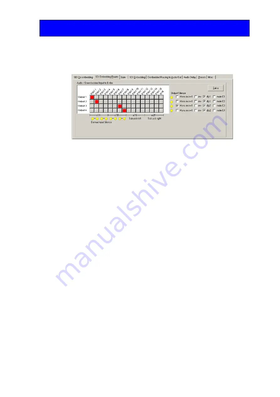
Side 1 Embedding Router for mode 1
Router sources appear in groups of four columns labelled input 1 to 16 above the columns
and with A and B demux codes and H and G input option codes underneath the columns.
The four router outputs are shown by the rows labelled Output 1 to 4 on the left of the
router display, whilst processing options are selected for each output with the check boxes
on the right of the display.
Assign source to destinations by clicking on the crosspoint squares in the matrix. Any
selections made will turn dark red. Invalid selections will be rejected and returned to the
last valid selection. Click on the Salvo button when finished. Valid selections will turn
bright red and new source-destination assignments will be loaded into the routing table.
Using the stereo to mono converters
TANDEM-300 has 8 built in stereo to mono converters that may be applied
independently to each adjacent pair of the embedding router inputs. If ‘Mono in in+1’ is
selected for any output row, the output will always be the sum of left-most (odd
numbered) audio source and its immediate neighbour on its right (next even numbered
source).
To reflect this operation, only left-most sources can be successfully highlighted when
Salvo is pressed when summed (mono) is applied to an output row. If a right-most input is
selected when an output row is in mono mode and Salvo is pressed, only the left-most
input of the pair will be highlighted.
When an output row is in normal stereo mode (Mono in in+1 not ticked), either the left-
most or the right-most audio channel of an adjacent pair can be selected (but not both).
Note:
The TANDEM-300 router does not support summing input channels unless they are left-
most/right-most pairs. For example, it is not possible to select input 1 + input 3, only
input 1 + input 2 OR input 3 + input 4.
Applying delay, phase inversion and mute
Check the ‘inv’ box to apply a phase inversion to an output and dly1/dly 2 to apply the
delay configured using the delay tab menu. Check ‘mute’ to output silence (zero gain) for
selected output row.


