


68
Cranesmart LMI Version R9
Permissions Level
To access these menu selections you must use the Supervisor Permi
ssion code of “111” at the permission screen
To Set the Permission Level
1. From the Primary Operating screen press select, the Secondary Operating screen is displayed.
2. Use the Up or Down arrows, select Setup.
3. Use the Up or Down arrows, select System.
4. Use the Up or Down arrows, select Permission.
5. Press Select button and use the Up or Down arrows to scroll to the permission code (111).
6. Press Accept twice to save.
7. You will be automatically taken to the Top Menu where you can select from the functions available.
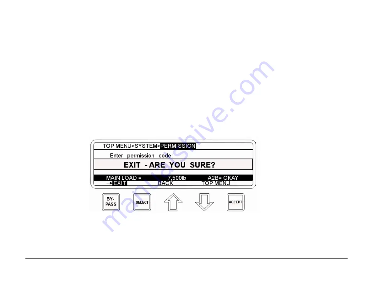
To Exit the Setup Menu
1. If you select Exit a message will be displayed to verify that you want to exit.
2. Press Accept to Exit. If you press Select a message will be displayed to Press Accept to Exit.
NOTE:
If the Accept key is pressed the system will return to the Primary Operating Screen and return to the Operator permission level.
If the supervisor does not want to exit pressing the Up or Down arrows will cancel the exit.
The Supervisor Permission code can be changed by the user to limit access if necessary. Please call our Service department for more information
Содержание LMI System
Страница 1: ...Cranesmart Systems LMI System User Manual May 11 2015 Rev 9...
Страница 23: ...22 Cranesmart LMI Version R9...
Страница 43: ...42 Cranesmart LMI Version R9 Basic Wiring Diagram...
Страница 45: ...44 Cranesmart LMI Version R9 Junction Box Wiring Diagram...
Страница 47: ...46 Cranesmart LMI Version R9 Alarm Hub Wiring Diagram...
Страница 91: ...90 Cranesmart LMI Version R9 Technical Specifications 7 500lb single line pull load cell...
Страница 92: ...91 Cranesmart LMI Version R9 15 000 single line pull load cell...
Страница 93: ...92 Cranesmart LMI Version R9 25 000lb single line pull load cell...
Страница 94: ...93 Cranesmart LMI Version R9 40 000lb single line pull load cell...
Страница 95: ...94 Cranesmart LMI Version R9 50 000lb single line pull load cell...
Страница 96: ...95 Cranesmart LMI Version R9 80 000lb single line pull load cell...
Страница 97: ...96 Cranesmart LMI Version R9 Anti 2 Block Switch...
Страница 98: ...97 Cranesmart LMI Version R9 Boom Angle Transducer...
Страница 99: ...98 Cranesmart LMI Version R9 Display Panel...
Страница 100: ...99 Cranesmart LMI Version R9 Alarm Hub...
Страница 101: ...100 Cranesmart LMI Version R9 Wind Speed Transducer...


