


8
MYDENS 60
COSMOGAS
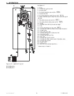
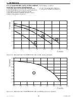
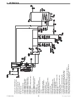
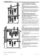
Key figure 4.1:
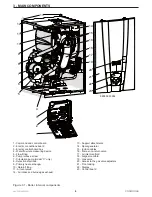
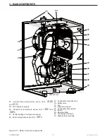
1 = Boiler
2 = Combustion agent air inlet
3 = Fumes outlet
4 = Fumes temperature sensor (Par.
1006
)
5 = Sealed chamber
6 = Fumes temperature safety sensor (Par.
1014
)
7 = Water collection pipe coming from the combustion agent
inlet pipe
8 = Flow temperature sensor (Par.
1001
)
9 = Flow temperature safety sensor (Par.
1005
)
10 = Burner
11 = Stainless steel VRC type heat exchanger
12 = Fan
13 = Return temperature sensor (Par.
1007
)
14 = Condensate collection siphon with sediment decanter
15 = Air/gas mixer
16 = Pneumatic gas valve
17 = Central heating circuit pressure sensor
18 = Circulation pump *
19 = Central heating circuit flow
20 = Gas inlet
21 = Central heating circuit return
22 = Condensate drain collector and of the safety valve
23 = Central heating plant
24 = Air vent valve
25 = Safety valve
26 = Water flow rate measuring device
* Present only in model C
4 - OPERATION
Figure 4.1 - Hydraulic layout
MYDENS 60A
MYDENS 60C
Содержание MYDENS 60
Страница 63: ...63 MYDENS 60 COSMOGAS 8 MAINTENANCE ...
Страница 71: ......
Страница 72: ...COSMOGAS s r l Via L da Vinci 16 47014 MELDOLA FC ITALY info cosmogas com www cosmogas com ...


