


18
MYDENS 60
COSMOGAS
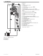
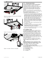
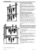
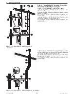
Figure 5.4 - Safety valve drain and condensate
drain connection
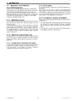
5 - INSTALLATION
5.11 - Condensate drain
There is a siphon inside the boiler for the evacuation of
condensate (see figure 3.1 detail “33”) and to prevent
combustion products from escaping, whose end
corresponds to the pipe “B” in figure 5.4. This termination
must be conveyed into an anti-odour siphon (figure
5.6 detail “G”) to prevent bad odours returning into the
environment (the anti-odour siphon “G” is supplied on
request).
The tank “A” is provided already mounted as indicated in
figure 5.4 and fixed with the screw “D”. The drain pipe “F” is
also installed as indicated in figure 5.4.
In particular, the condensate drain plant must be:
for room used for residential purposes and for office with
more than 10 users, it can be connected to the domestic
waste disposal plant by means of appropriate siphon with
disjunction capable of preventing the pressurisation of
the system (siphon prepared within boiler) and to prevent
the return of bad odours from the sewer (detail “G” in
figure 5.6). If the room used for office purposes has
less than 10 users, before connection with the domestic
waste drain, a condensate neutraliser is good practice
(see chapter 9 for the value of acidity of the condensate
and the quantities).
be performed with a pipe with internal diameter equal to
or greater than 13 mm;
be installed in a way to prevent the liquid from freezing;
therefore pay attention to any external passings. It is
prohibited to drain into gutters or drainpipes;
to slope continuously towards the drain point, avoid high
points, which could pressurise the pipe;
5.12 - Safety valve
The appliance is protected against overpressures by a
safety valve calibrated to 3 bar (see figure 3.1 detail “30”).
The safety valve drain (detail “C” in figure 5.4), along
with the condensate drain (detail “B” in figure 5.4) must
be conveyed to a pipe “F” (see figure 5.4) with minimum
internal diameter of 13 mm. The pipe “F” must be then
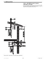
taken to the anti-odour siphon (detail “G” figure 5.6). This
drain with siphon is used to prevent overpressures if the
valve is opened and makes it possible for the user to check
the eventual intervention.
The pipe “F” in figure 5.6 is supplied mounted as per
standard along with tank “A” in figure 5.4. The anti-odour
siphon “G” in figure 5.6 is provided on request.
ATTENTION !!! If not connected to the drain,
whenever the safety valve should intervene, it could
cause damage to persons, animals or objects.
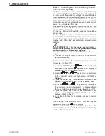
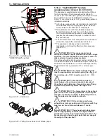
5.13 - Water, gas connections
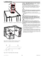
The boiler is provided with the fittings illustrated in figure 5.5
as per standard, where:
A = central heating flow Ø 35
B = central heating return Ø 35
C = 1” 1/2 flow fitting
D = 1” 1/2 return fitting
E = 1”1/2 Gasket
Figure 5.5 - Hydraulic connections
C
A
E
D
B
020005.01.005
Figure 5.6 - Siphon funnel (on request)
F
G
020002.01.028
min10 mm
max 30 mm
C
B
A
D
G
F
E
020005.01.004
Содержание MYDENS 60
Страница 63: ...63 MYDENS 60 COSMOGAS 8 MAINTENANCE ...
Страница 71: ......
Страница 72: ...COSMOGAS s r l Via L da Vinci 16 47014 MELDOLA FC ITALY info cosmogas com www cosmogas com ...


