


17
MYDENS 60
COSMOGAS
5 - INSTALLATION
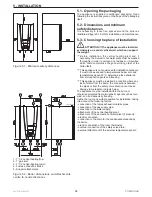
5.6.3 Treatment of the water in the thermal
plants for civil use
The water in the heating plants for civil use must always be
treated on replacement of the generator and in the event of
a new plant.
On the basis of the features of the raw water, in the design
phase all treatment plants and the chemical conditioners
necessary to obtain water with the following features, must
be envisioned:
- Aspect: possibly clear;
- pH: over 7 (with radiators with aluminium elements of light
alloys, the pH must be lower than 8.5);
- Conditioners: present within the concentrations prescribed
by the supplier.
If the features of the of the water are not known, the probability
of the following typical drawbacks occurring is high:
1. LIME SCALE FOULING
1 °fr = 10mg/kg CaCO
3
30° fr = 300 mg/kg CaCO
3
In a plant that contains 1000 litres of water at 30°f, the content
of CaC03 is equal to 300 gr, which if not treated suitably,
will deposit on the surface of the heat exchanger as this
is the hottest point of the plant. This creates concentrated
temperature increases with consequent breakage of the heat
exchanger.
2. CORROSION
Corrosion is normally promoted by the presence of oxygen,
by the contact between different metals or the presence of
chlorides.
3. DEPOSITS
They are insoluble organic and inorganic substances:
SLUDGE, WORKING RESIDUES.
5.7 - Draining the heating circuit
To avoid continuous renewal of water and consequent input
of oxygen and limestone, it is recommended to limit every
heating circuit drainage as much as possible.
5.8 - Expansion Tank
ATTENTION !!! Provide the plant with an
appropriately dimensioned expansion tank, as
envisioned by the national and local Installation
Standards.
5.9 - Low temperature
plants (or on the floor)
ATTENTION !!! The plant downstream from
the appliance must be made with materials that
resist temperatures up to 97°C and pressure of 3 bar.
Differently (e.g. plastic piping) the plant must be fitted
with the relevant protection and safety devices.
ATTENTION !!! when installing the boiler in
a low temperature plant, it is indispensable to set
parameter
3015
at the value of 45°C and parameter
3016
at the value of 20°C (see chapter 11).
With this setting, the boiler will adjust the flow to a
temperature between 20°C and 45°C. No adjustment from
the command panel (also via climatic adjustment),can
supply water at a temperature over 45°C.
ATTENTION !!! If the boiler is installed in a floor
plant made with plastic piping, all of the precautions
must be taken against corrosion due to oxygen in the
water:
make sure that the plant is made with plastic pipes with
permeability to oxygen not exceeding 0.1 g/m3 at 40°C.
Whenever the pipe should not meet these features, the
radiant panel circuit from the boiler must be isolated via
a plate heat exchanger, suitable to resist the corrosion
generated by the oxygen dissolved in the water.
5.10 - Gas
ATTENTION !!! It is prohibited to power the
appliance with gases different to that envisioned.
ATTENTION !!! Check that the gas and supply
pressure are those for which the boiler has been
adjusted.
Two situations are possible:
A - the gas and supply pressure correspond to the
adjustment of the boiler. In this case, it can be
connected;
B - the gas and supply pressure do not correspond to the
adjustment of the boiler. In this case, the boiler must
be converted to the type of gas and supply pressure
corresponding to the supply available.
The boiler is provided with the relevant gas conversion kit.
Before installation it is advised to clean the inside of the
gas supply pipe thoroughly;
A cut-off cock must always be installed on the gas
supply pipe;
To prevent damage to the appliance gas control unit,
perform the leak test at a pressure not exceeding 50
mbar;
If the gas plant must be inspected at pressures over
50 mbar, operate on the cock positioned immediately
upstream from the boiler, to isolate the same from the
plant.
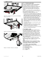
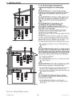
Figure 5.2 verifies the positioning of the appliance gas fitting.
The sections of the pipes making up the gas supply plant
must always guarantee a gas supply sufficient to cover the
maximum requested.
Содержание MYDENS 60
Страница 63: ...63 MYDENS 60 COSMOGAS 8 MAINTENANCE ...
Страница 71: ......
Страница 72: ...COSMOGAS s r l Via L da Vinci 16 47014 MELDOLA FC ITALY info cosmogas com www cosmogas com ...


