background image

Betriebsanleitung 

Artiglio Master

 135

D


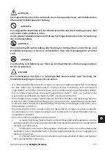
ACHTUNG


Für Folgeschäden durch den Gebrauch von nicht originalen Ersatz- und Zubehörteilen 
übernimmt CORGHI keinerlei Haftung.


ACHTUNG


Der eingestellte Betriebsdruck der Überdruckventile und des Druckbegrenzers darf 
auf keinen Fall verändert werden.
Der Hersteller übernimmt keinerlei Haftung bei Folgeschäden durch die Veränderung 
der Ventileinstellung.


ACHTUNG


Vor jedem Eingriff zur Einstellung oder Wartung ist die Maschine von der Strom- und 
Druckluftversorgung zu trennen; sicherstellen, dass alle Bewegungsteile arretiert 
sind.


ACHTUNG


Die Abnahme und Änderung von Teilen an der Maschine ist verboten (ausgenommen 
für Servicearbeiten).


GEFAHR

Die Vorrichtungen mit dem o.a. Gefahrenschild können selbst nach Trennung der 
Druckluftversorgung noch unter Druck stehen.

-  Die Filter-Regel-Schmiersystem-Gruppe ist mit einer halbautomatischen Vorrichtung 

für den Ablass des Kondenswassers versehen. Diese Vorrichtung wird automatisch 
zugeschaltet, sobald die Unterbrechung der Druckluftversorgung der Maschine erfolgt. 
Der Kondenswasserablass ist manuell auszuführen (Taste 1, Abb. 22), nachdem der 
Kondenswasserfüllstand die Marke X (Abb. 22) überschritten hat.

-  Einmal täglich die korrekte Funktionsweise der Gleitschrauben des Werkzeug-Montier-

kopfs und jeder Wulstabdrück-Baugruppe überprüfen. Die Ansammlung von Schmutz 
in diesem Bereich kann den einwandfreien Betrieb beeinträchtigen und somit zu Ge-
fahrensituationen führen.

- Einmal wöchentlich den oberen Teller des Spannfutters reinigen: Hierbei eventuelle 

Ansammlungen von Schmutz beseitigen und den Bereich mit umweltfreundlichen Lö-
sungsmitteln säubern.

- Einmal monatlich auszuführende Kontrollen:

•  

Arme des Werkzeug-Montierkopfs und jeder Wulstabdrück-Baugruppe sowie die 

entsprechenden Gleitschrauben ausschließlich mit umweltfreundlichen Lösungsmitteln 
reinigen und schmieren.

•  

Ölfüllstand in der Luft-Schmiergruppe überprüfen (Abb. 22) und bei Bedarf das 

Nachfüllen mit Öl der Marke SAE20 ohne Reinigungswirkstoffe bis zur angegebenen 
Marke Z vornehmen.

•  

Die Reinigung ist mit einem trockenen Lappen auszuführen. Hierbei den Kontakt 

mit Lösungsmitteln vermeiden.

Содержание Artiglio Master 26 MI

Страница 1: ...03084G 04 2018 Tel 39 0522 639 111 Fax 39 0522 639 150 www corghi com info corghi com Italiano Manuale d uso 3 English Operator s manual 39 Fran ais Manuel d utilisation 73 Deutsch Betriebsanleitung 1...

Страница 2: ...oncompl teoupartiellepartout typedemoyen ycomprismicrofilmsetcopiesphotostatiques sont r serv s Les informations fournies dans ce manuel peuvent tre modi fi es tout moment et sans pr avis Alle Rechte...

Страница 3: ...E PREVISTE 13 Posizione dell operatore 14 PRINCIPALI ELEMENTI DI FUNZIONAMENTO 14 Comandi 15 Legenda etichette di pericolo 18 STALLONATURA 18 Controlli preliminari 18 Accensione della macchina 18 Come...

Страница 4: ...dite d olio 30 Precauzioni nell impiego dell olio 30 Olio minerale indicazioni di pronto soccorso 30 MEZZI ANTINCENDIO DA UTILIZZARE 31 GLOSSARIO 31 SCHEMA ELETTRICO 35 SCHEMA PNEUMATICO 36 Schema imp...

Страница 5: ...vendita dell apparecchiatura tutta la documentazione dovr esservi allegata Il manuale da ritenersi valido esclusivamente per il modello e la matricola macchina rilevabili dalla targhetta applicata su...

Страница 6: ...versione STD kg 530 versione T I kg 545 Condizioni dell ambiente di trasporto e stoccaggio macchina Temperatura 25 55 C ATTENZIONE Per evitare danneggiamenti non sovrapporre altri colli sull imballo...

Страница 7: ...5 mettendoliinposizione tale da evitare che possano cadere e danneggiarsi Montare il gruppo sollevatore 4 lateralmente al cassone bloccando con viti e rondelle A Rimuovere la carteratura perimetrale d...

Страница 8: ...rativa Tale piano deve avere una portata di almeno 500 kg m2 Condizioni ambientali di lavoro Umidit relativa 30 95 senza condensazione Temperatura 0 C 50 C ATTENZIONE Non ammesso l utilizzo della macc...

Страница 9: ...ua al filo del telefono o ad altri oggetti non idonei Verificare che la pressione e la portata rese disponibili dall impianto dell aria compressa siano compatibili con quelle richieste per il buon fun...

Страница 10: ...vi sia una supervisione adeguata Non dimenticare mai sulla macchina dadi bulloni utensili od altro che durante il lavoro potrebbero inserirsi tra parti in movimento della macchina stessa Non toccare l...

Страница 11: ...o verticale bidirezionale con pene trazione controllata a comando automatico una torretta portautensili con movimento verticale bidirezionale comandata da consol le che consente il montaggio e lo smon...

Страница 12: ...ensili automatico appoggio flangiato centraggio su cono bloccaggio automatico coppia di rotazione 1100 Nm velocit di rotazione 7 18 rpm Gruppo Stallonatore utensile disco posizionamento rispetto al ce...

Страница 13: ...pericolo e del rischio ACCESSORI A RICHIESTA Per l elenco esecutivo degli accessori a richiesta si rimanda al libretto ACCESSORI ORI GINALI per SMONTAGOMME ARTIGLIO MASTER fornito in dotazione alla m...

Страница 14: ...re installata adeguatamente azionata in modo corretto e sottoposta a pe riodica manutenzione I principali elementi di funzionamento della macchina sono rappresentati in fig 8a e fig 8b 1 Cassone 2 Sol...

Страница 15: ...el diametro del cerchio Display di visualizzazione del diametro del cerchio in pollici La cifra visualizzata di due cifre con separatore decimale 4 Tastiera impostazione diametro cerchio La tastiera s...

Страница 16: ...le mobile del tallone superiore del pneumatico 7 Leva di comando movimenti torretta Levacheconsentedieseguirelospostamentodellatorrettaportautensililungo4direzioni alto basso avanzamento arretramento...

Страница 17: ...lia di centraggio all auto centrante Nellasuaposizionediriposoilsistemadibloccaggiodellamanigliadicentraggio all autocentrante normalmente attivo Il pedale si utilizza nella fase di predisposizione e...

Страница 18: ...china Alimentare elettricamente la macchina agendo sull interruttore generale di colore verde 1 fig 9d posto sul coperchio della cassetta elettrica Pereseguirel accensionedellamacchina premerel interr...

Страница 19: ...ssimo o addirittura mancante fig 10a Questi cerchi non risultano approvati secondo i criteri DOT Department of Trasportation sigla che certifica la conformit del pneumatico agli standards di sicurezza...

Страница 20: ...l pneumatico togliendo la valvola Predisporre in posizione di lavoro asse braccio orizzontale il gruppo stallonatore superiore abbassandolo manualmente mediante l apposita leva fissa di presa Agire su...

Страница 21: ...ello stesso frangente l autocentrante si avvicina alla parte tesa scaricando il pneumatico dalle tensioni generatesi nella sua struttura Mantenendo ruotato il selettore 6 fig 9b premere il Pedale 1 fi...

Страница 22: ...lo stesso Le caratteristiche dimensionali e di costruzione e le caratteristiche di servizio sono indivi duabili attraverso l interpretazione delle diciture riportate sul fianco della copertura Scelta...

Страница 23: ...superiore Fare avanzare l utensile fisso sino a fine corsa e abbassarlo sino a farlo interporre tra la balconata superiore del cerchio ed il tallone superiore della copertura La corretta posizione ver...

Страница 24: ...dal fabbricante del pneumatico I pneumatici possono esplodere se vengono gonfiati oltre questi limiti o possono danneggiarsi gravemente nelle strutture in modo non visibile sul momento TENERE LE MANI...

Страница 25: ...9b e rimuovere la ruota dalla zona di lavoro Con sollevatore a terra prelevare la ruota pronta per il suo successivo montaggio sul veicolo Gonfiaggio pneumatici con camera d aria tube type Assicurarsi...

Страница 26: ...ei pneumatici quando questi sono caldi Sipossonoritenerefreddiqueipneumaticichenonsonostatiimpiegatidaalmenoun ora ovvero hanno percorso a bassa velocit non pi di 2 o 3 chilometri Le pressioni di gonf...

Страница 27: ...tocentrante togliereeventualiaccumuli di sporcizia e pulire con solventi compatibili con l ambiente Controlli mensili Pulire e lubrificare solo con solventi compatibili con l ambiente i bracci della t...

Страница 28: ...cnica ENC SEGNALE DI ENCODER COMPARE QUANDO LA SCHEDA NON RICEVE SEGNALI DALL ENCODER DURANTE LA FASE DI AZZERAMENTO A 26 POLLICI Potrebbeesserenecessariosostituirel attuatore laschedaoilcavodell enco...

Страница 29: ...o sul prodotto ed in questa pagina ricorda la necessit di smaltire adeguatamente il prodotto al termine della sua vita In tal modo possibile evitare che un trattamento non specifico delle sostanze con...

Страница 30: ...one o la diffusione di nebbie d olio nell atmosfera Adottare quindi le seguenti elementari precauzioni igieniche evitare gli schizzi indumenti appropriati schermi protettivi sulle macchine lavarsi fre...

Страница 31: ...umatici tube type IV aria in pressione Il pneumatico deve sostenere il carico assicurare la trasmissione delle potenze motrici dirigere il veicolo contribuire alla tenuta di strada ed alla frenatura c...

Страница 32: ...arcassa radiale pura e semplice relativamente instabile perrenderlastabileeimpediremovimenti parassiti del battistrada nell area di contatto con il terreno sullacarcassaesottoalbattistradasidispone un...

Страница 33: ...venzionale con l ultima tela di carcassa 13 Spalla E lazonaestremadelbattistradacompresa tra lo spigolo e l inizio del fianco 14 Tallone E la parte di accoppiamento tra la co pertura e il cerchio La p...

Страница 34: ...ntrale h interasse fori attacco i diametro di calettamento j canale III Camera d aria in pneumatici tube type Lacamera d aria un involucro di gomma chiuso ad anello e munito di valvola che ha il compi...

Страница 35: ...re TC1 FU8 Fusibile 5x20 H T 3 15A su AP2 FU9 Fusibile 5x20 H T 1A su AP2 FU10 Fusibile 5x20 H T 16A su AP2 FU11 Fusibile 5x20 H T 16A su AP2 HL1 Spia su interruttore M1 Motore M2 Motore c c traslazio...

Страница 36: ...allonatore inferiore D MOVIMENTO TESTINA UTENSILE 19 Valvola 3 2 NO 20 Valvola 3 2 NC 21 Cilindro movimento testina utensile E ROTAZIONE TESTINA UTENSILE 22 Valvola 5 2 23 Cilindro rotazione utensile...

Страница 37: ...Valvola 5 3 2 Filtro silenziatore 3 Valvola 3 vie 4 Cilindro sollevamento 5 Cilindro rotazione 6 Valvola regolatore di flusso bidirezionale 7 Intercettore di blocco Schema impianto pneumatico Alzatall...

Страница 38: ...38 Manuale d uso Artiglio Master Note...

Страница 39: ...IONAL ACCESSORIES 49 SPECIFIED CONDITIONS OF USE 49 Operator position 50 MAIN OPERATING PARTS 50 Controls 51 Key to danger warning decals 53 BEAD BREAKING 54 Preliminary checks 54 Switching on the mac...

Страница 40: ...Oil spills and leaks 64 Precautions when using oil 64 Mineral oil first aid procedures 64 RECOMMENDED FIRE EXTINGUISHING DEVICES 65 GLOSSARY 66 WIRING DIAGRAM 70 PNEUMATIC DIAGRAM 71 General pneumati...

Страница 41: ...vent of sale all relative documentation must remain with the tyre changer The manual is only to be considered valid for the machine of the model and with the serial number indicated on the nameplate a...

Страница 42: ...of packaging in wood STD version 530 kg T I version 545 kg Ambient conditions for storage and transport Temperature 25 55 C WARNING Do not stack other goods on top of the packaging or damage may resu...

Страница 43: ...nk 3 or the optional units 4 and 5 and place them in a position where they cannot fall over and be damaged Fit the wheel lift unit 4 on the side of the body securing it with the screws and washers A R...

Страница 44: ...ty of at least 500 kg m2 Ambient conditions for operation Relative humidity 30 95 without condensation Temperature 0 C 50 C WARNING The machine must not be operated in a potentially explosive atmosphe...

Страница 45: ...unsuitable objects Check that the pressure and flow rate provided by the compressed air system are com patible with those required for proper operation of the machine see Technical Data section Forco...

Страница 46: ...compliance with all relevant regulations and legislation Make sure that all machine operators are suitably trained that they are capable of using the equipment correctly and that they are adequately...

Страница 47: ...erunitwithtwoautomaticallyoperated controlled penetration vertical two way discs a tool head with two way vertical movement controlled from the console allowing op timum tyre mounting and demounting w...

Страница 48: ...utomatic speed torque 1100 Nm rotation speed 7 18 rpm Bead Breaker Unit tool disc positioning in relation to rim automatic penetration guided maximum bead breaking range 18 top bead breaker stroke 450...

Страница 49: ...OPTIONAL ACCESSORIES For the full list of optional accessories for the ARTIGLIO MASTER TYRE CHANGER refer to the ORIGINAL ACCESSORIES handbook supplied with the machine SPECIFIED CONDITIONS OF USE ART...

Страница 50: ...tly and serviced regularly The machine s main operating parts are shown in fig 8a and fig 8b 1 Body 2 Wheel lift optional accessory 3 Support optional accessory 4 Centring handle device for clamping t...

Страница 51: ...figures Use these keys to enter the value of the decimal figures by increasing or decreasing the value set 5 Deflation button Press this button to discharge excess air from inside the tyre This button...

Страница 52: ...tion on the turntable to the ground While the pneumatic wheel lift is ascending or descending a beeper warns the operator that the procedure is in progress 9 Pneumatic support operating lever Leverwhi...

Страница 53: ...e still does not work after all the above conditions have been met try moving the tool head to the working position since there is no position microswitch the circuit board does not recognise the prec...

Страница 54: ...ss any of the numerical value input keys on the Keypad 4 Fig 9a The turntable and the two units with bead breaker disc automatically reset in the radial position suitable for processing 26 rims The ma...

Страница 55: ...s separated by a decimal point As this value is set both the self centring turntable and the two units with bead breaker disc automatically move to the ideal radial position for performing the job Loa...

Страница 56: ...15b Now press the Button 5 fig 9b to obtain a grip on the top bead of the tyre fig 15c If necessary turn the wheel to allow this by pressing Pedal 1 fig 9c Once the grip has been established release t...

Страница 57: ...lace the tyre for changing on the ground by hand TYRE MOUNTING Instructions for choosing the tyre To obtain full benefit from the characteristics offered by a tyre and to obtain the neces sary guarant...

Страница 58: ...guide the tool head into the working zone to mount the top bead While the head is moving push or pull the Switch 4 fig 9b to prepare the fixed tool 7 fig 8a to mount the top bead Move the fixed tool f...

Страница 59: ...time KEEP THE HANDS AND THE WHOLE BODY WELL AWAY FROM THE TYRE DURING INFLATION Make sure you are concentrated during this operation and check the tyre pressure continuously to avoid excess inflation...

Страница 60: ...breaker units 9 13 fig 8a are well clear of the working area if possible in the rest position Connect the Doyfe union of the inflation line 20 fig 8b to the stem of the inner tube val ve after removi...

Страница 61: ...G The Spare Parts manual does not authorise the user to do any work on the machine except for that specifically described in the operator s manual but does enable the user to provide accurate informat...

Страница 62: ...the transparent cap K correct flow rate 1 drop of oil every 4 bead breaking cycles Adjust if necessary by turning the adjuster screw Y fig 22 ATTENTION Keep the working area clean Never use compresse...

Страница 63: ...nnection of the end of stroke microswitches and check if one of them is broken Contact technical service if necessary ROT INCORRECT ROTATION DIRECTION SIGNAL THIS APPEARS WHEN THE ENCODER CHANNELS ARE...

Страница 64: ...will also inform you of the possibility to return free of charge another end of life equipment as long as it is of equivalent type and has fulfilled the same functions as the supplied equipment Adispo...

Страница 65: ...o protect against oil splashes Mineral oil first aid procedures Swallowing seek medical attention providing the characteristics of the type of oil swallowed Inhalation in case of exposure to high conc...

Страница 66: ...and a good grip on the ground in wet and dry conditions as well as low running noise 2 Edge or reinforcement A woven metal or fabric insert on the outside of the bead it protects the carcass plies fro...

Страница 67: ...e tyre is centred exactly on the rim after mounting 7 Guard ridge This is a ridge running around the circumference of the part of the sidewall most at risk of accidental rubbing 8 Sidewall This is the...

Страница 68: ...known as a liner This helps to ensure that the pressurised air inside the carcass is retained This type of tyre has to be mounted on a special rim to which the valve is fixed directly II Rim Wheel Th...

Страница 69: ...ht seal an internal mechanism b and the base c outer coating TubelessInflator Aninflationsystemwhich simplifies the inflation of tubeless tyres Bead insertion Operation which takes place during inflat...

Страница 70: ...H T 16A fuse on AP2 HL1 Switch indicator M1 Motor M2 Vertical movement DC motor M4 Linear actuator encoder QS1 Two pole switch SB4 Demounting selector SQ5 Micro switch speed I CLOCKWISE SQ6 Micro swit...

Страница 71: ...losed 18 Bottom bead breaker cylinder D TOOL HEAD MOVEMENT 19 3 2 valve normally open 20 3 2 valve normally closed 21 Tool head movement cylinder E TOOL HEAD ROTATION 22 3 way valve 23 Tool rotation c...

Страница 72: ...N 4 104715 Fig 31 1 5 3 valve 2 Silencer filter 3 3 way valve 4 Lifting cylinder 5 Rotation cylinder 6 Two way flow regulator valve 7 Cut off valve Bead lifter pneumatic plant diagram Sheet N 463533 F...

Страница 73: ...ES 83 Position de l op rateur 84 PRINCIPAUX ELEMENTS DE FONCTIONNEMENT 84 Commandes 85 L gende des tiquettes de danger 88 DETALONNAGE 88 Contr les pr liminaires 88 Allumage de l appareil 88 Comment sa...

Страница 74: ...huile 100 Pr cautions lors de l utilisation de l huile 100 Huile min rale informations pour les secours d urgence 100 MOYENS ANTI INCENDIE A UTILISER 101 LEXIQUE 102 SCH MA LECTRIQUE 106 SCH MA PNEUM...

Страница 75: ...agner ce dernier Ce manuel est valable exclusivement pour le mod le et le num ro de s rie de l appareil report s sur la plaquette appliqu e celui ci ATTENTION Respecter scrupuleusement les instruction...

Страница 76: ...version standard 530 Kg version T I 545 kg Conditions du lieu de transport et de stockage de l appareil Temp rature 25 55 C ATTENTION Pour viter toute d t rioration ne pas superposer d autres colis l...

Страница 77: ...es groupes optionnels 4 et 5 Les mettre dans une position telle qu ils ne puissent pas tomber et s endommager Monter le groupe l vateur 4 lat ralement la carcasse en bloquant avec les vis et les ronde...

Страница 78: ...smises pendant la phase op rationnelle Ce plan doit avoir une capacit de charge d au moins 500 kg m2 Conditions d environnement du travail Humidit relative 30 95 sans condensation Temp rature 0 C 50 C...

Страница 79: ...az de l eau au fil du t l phone ou d autres objets inappropri s V rifier que la pression et le d bit rendus disponibles par l installation de l air comprim soient compatibles avec ceux n cessaires au...

Страница 80: ...t form s qu ils savent utiliser l ap pareil correctement et en toute s curit et qu il existe une supervision appropri e ne jamais oublier les crous boulons outils ou autres objets sur l appareil car p...

Страница 81: ...t innovateur pr voit la pr s lection lectronique du diam tre de la jante avec positionnement radial auto matique des outils de montage et de d montage et des disques d talonneurs un groupe d talonneur...

Страница 82: ...LE RUN FLAT Plage des dimensions de la roue diam tre de la jante de 12 26 diam tre maxi du pneumatique 1100 mm largeur maxi du pneumatique 360 mm 14 Mandrin positionnement par rapport aux outils autom...

Страница 83: ...s niveaux d exposition consentis peuvent changer d un pays l autre De toute fa on ces informations permettront l utilisateur de l appareil d effectuer une meilleure valuation du danger et du risque AC...

Страница 84: ...e l appareil en conna tre le fonctionnement exact est la meilleure garantie de s curit et de performances Apprendre la fonction et la disposition de toutes les commandes Contr ler minutieusement le fo...

Страница 85: ...affichage des donn es de la roue voir fig 9a 1 Manom tre d affichage de la pression de l air Manom tre d affichage de la pression de l air r gl avec la p dale 3 fig 9c Affiche la pression en bars du...

Страница 86: ...En lib rant le bouton l outil retourne sa position de repos 6 S lecteur position instable d actionnement de l outil mobile pour le d montage du talon sup rieur Tourner le s lecteur pour actionner l ou...

Страница 87: ...dale de blocage de la roue La p dale lib re si elle est press e le syst me de blocage de la poign e de centrage au mandrin Dans sa position de repos le syst me de blocage de la poign e de centrage au...

Страница 88: ...eil au r seau lectrique ait t effectu correc tement Allumage de l appareil Alimenter lectriquement l appareil en agissant sur l interrupteur g n ral de couleur verte 1 fig 9d plac sur le couvercle du...

Страница 89: ...iage avec creux A tr s r duit ou m me manquant fig 10a Ces jantes ne sont pas approuv es selon les crit res DOT Department of Trasportation sigle qui certifie la conformit du pneumatique aux standards...

Страница 90: ...la valve Mettre en position de travail axe bras horizontal le groupe d talonneur sup rieur en le baissant manuellement l aide du levier fixe de prise Agir sur le Levier 1 fig 9b en portant le disque p...

Страница 91: ...ndrin se rapproche de la partie tendue en d chargeant le pneumatique des tensions qui se sont cr es dans sa structure En tenant tourn le S lecteur 6 fig 9b appuyer sur la P dale 1 fig 9c de rotation d...

Страница 92: ...a couverture Lorsqu on a choisi la couverture appropri e parmi celles admises pour l quipement du v hicule on peut passer aux phases op rationnelles AVERTISSEMENT Au montage d une nouvelle couverture...

Страница 93: ...et le baisser jusqu ce qu il s interpose entre le bord sup rieur de la jante et le talon sup rieur de la couverture La position verticale correcte de l outil fixe est lorsque le rep re existant sur ce...

Страница 94: ...ricant du pneumatique Les pneumatiques peuvent exploser s ils sont gonfl s au del de ces limites ou leurs structures peuvent s endommager gravement sans que l on s en aper oive premi re vue NE PAS APP...

Страница 95: ...fig 9c Agir sur le Levier 8 fig 9b et enlever la roue de la zone de travail Avec l l vateur au sol pr lever la roue pr te pour son montage successif sur le v hicule Gonflage de pneumatiques avec chamb...

Страница 96: ...matiques qui ne sont plus utilis s depuis au moins une heure ou bien s ils ont parcouru basse vitesse moins de 2 ou 3 kilom tres Les pressions de gonflage froid doivent correspondre celles prescrites...

Страница 97: ...et et nettoyer avec des solvants compatibles avec l environne ment Contr les mensuels Nettoyer et lubrifier seulement avec des solvants compatibles avec l environnement les bras de la tourelle porte o...

Страница 98: ...IL S AFFICHE LORSQUE LA CARTE NE RECOIT PLUS DE SIGNAUX DU CO DEUR PENDANT 2 SECONDES APRES L EFFACEMENT A 26 POUCES Il pourrait s av rer n cessaire de remplacer l actionneur la carte ou le c ble du...

Страница 99: ...la poubelle barr e appos sur le produit et illustr ci contre indique la n cessit de proc der l limination particularis e du produit au terme de sa vie De la sorte il est possible d viter qu un traitem...

Страница 100: ...de brouillards d huile dans l atmosph re Prendre les pr cautions l mentaires d hygi ne suivantes viter les claboussures v tements appropri s crans de protection sur les appa reils se laver fr quemmen...

Страница 101: ...es Appareils lectriques Hydrique OUI NON NON Mousse OUI OUI NON Poudre OUI OUI OUI CO2 OUI OUI OUI OUI Utilisable en l absence de moyens appropri s ou pour de petits incendies ATTENTION Les indication...

Страница 102: ...constitu e d un m lange de caoutchouc et d un dessin pouvant garantir une bonne r sistance l abrasion et une bonne adh rence au sol que celui ci soit sec ou mouill ainsi qu une marche silencieuse 2 B...

Страница 103: ...e C estunestructureencercleinextensible compos e de toiles crois es angles tr s bas positionn e sous la bande de roulement dans le but de stabiliser la carcasse dans la zone d empreinte 6 Lignedecentr...

Страница 104: ...nir l air en pression pour un temps assez long on utilise la chambre air l int rieur de la couverture La valve pour l introduction l tanch it le contr le et le r tablissement de l air en pression dans...

Страница 105: ...ure danslecasdestubeless Elleestcompos edetrois pi ces Lecapuchondefermeturedelavalve a pour prot ger de la poussi re son m canisme interne et garantir l tanch it l air un m canisme interne b et le fo...

Страница 106: ...n sur interrupteur M1 Moteur M2 Moteur c c translation verticale M4 Actionneur lin aire codeur QS1 Interrupteur bipolaire SB4 S lecteur d montage SQ5 Micro interrupteur I vitesse rotation sens HORAIRE...

Страница 107: ...8 V rin d talonneur inf rieur D MOUVEMENT T TE D OUTIL 19 Soupape 3 2 normalement ouverte 20 Soupape 3 2 normalement ferm e 21 V rin mouvement t te d outil E ROTATION T TE D OUTIL 22 Soupape 3 voies 2...

Страница 108: ...15 Fig 32 1 Soupape 5 3 2 Filtre du silencieux 3 Soupape 3 voies 4 V rin de levage 5 V rin rotation 6 Soupape r gulateur de flux bidirectionnelle 7 Vanne d arr t Sch ma installation pneumatique l ve t...

Страница 109: ...AGE 119 VORGESEHENER GEBRAUCH 120 Bedienstand des Anwenders 120 WESENTLICHE BETRIEBSELEMENTE 121 Steuer Bedienvorrichtungen 122 Legende der Warnetiketten 124 ABDR CKEN 125 Vor berpr fungen 125 Einscha...

Страница 110: ...entsorgung 138 Auslaufen oder Leckage von l 138 Vorsichtsma regeln beim Umgang von l 138 Mineral l Hinweise zur Ersten Hilfe 138 BRANDSCHUTZMITTEL 139 SACHBEGRIFFE 140 SCHALTPLAN 144 DRUCKLUFTPLAN 145...

Страница 111: ...ufzubewahren Die mitgelieferte technische Dokumentation ist integrierender Bestandteil der Maschine und muss dieser beim Verkauf beigef gt werden Das Handbuch besitzt ausschlie lich f r das Maschinenm...

Страница 112: ...gebenen Position transportiert werden Abmessungen der Verpackung Breite mm 1240 Tiefe mm 1500 H he mm 1840 Verpackungsgewicht aus Holz STD Version kg 530 T I Version kg 545 Umgebungsbedingungen f r Tr...

Страница 113: ...optionalen Baugruppen 4 und 5 ent fernen die ausgepackten Teile entsprechend anordnen sodass sie weder fallen noch besch digt werden k nnen Radheber Baugruppe4seitlichamMaschinenaufbauanbringenundmit...

Страница 114: ...kturierten B den installieren Die Stellfl che der Maschine muss die w hrend des Betriebs bertragenen Belastungen aushalten Die vorgesehene Fl che muss demnach eine Tragf higkeit von mindestens 500 kg...

Страница 115: ...en anschlie en Sicherstellen dass der von der Druckluftanlage bereitgestellte Druck und der diesbe z gliche Durchsatz den vorgesehenen Daten zur Gew hrleistung des einwandfreien Maschinenbetriebs ents...

Страница 116: ...icherzustellen dass das gesamte Bedienungspersonal f r die korrekte und sichere Bedienung der Maschine geschult ist und hier ber Aufsicht gef hrt wird Schraubteile Werkzeuge oder andere Gegenst nde un...

Страница 117: ...den Betrieb der Maschine sind folgende Innovationen vorgesehen elektronische Vorwahl des Felgendurchmessers mit automatischer radialer Positionie rung der Montage Demontagewerkzeuge und Reifenabdr cks...

Страница 118: ...HE DATEN Abmessungen siehe Abb 6 L nge A 1635 mm L nge mit Radheber A 2160 mm Breite B 1200 mm H he H 1600 mm Vorgesehene Reifen HERK MMLICHE LOW PROFILE RUN FLAT Bereich der Radma e Felgendurchmesser...

Страница 119: ...r aus gesetzt sind k nnen die Angaben nicht zuverl ssig f r die Bestimmung der Ergreifung weiterer Schutzma nahmen herangezogen werden Zu den Faktoren f r die Bestimmung des Ger uschpegels dem der Anw...

Страница 120: ...en der Maschine halten ACHTUNG F r die Not Aus Schaltung der Maschine folgenderma en vorgehen Netzstecker aus der Steckdose ziehen Sperrventil zur Unterbrechung der Druckluftversorgung ausr cken Schne...

Страница 121: ...tur 9 Obere Reifenabdr ckscheibe 10 Display zur Eingabe und Anzeige der Raddaten siehe Abb 9a und entsprechende Beschreibung im Abschnitt STEUER BEDIENVORRICHTUNGEN 11 Hebel f r L sen der oberen Wulst...

Страница 122: ...9d 1 Hauptschalter Gr nfarbener Schalter mit zwei Stellungen und Positionierung auf dem Deckel des elek trischen Schaltkastens 1 Abb 9d Auf Stellung 0 ist die Spannungsversorgung der Maschine vom Net...

Страница 123: ...pannfutter zu verfahren Den Hebel dagegen nach unten ver setzen um den pneumatischen Radheber zu aktivieren und das auf dem Hebergestell angeordnete Rad von der Arbeitsposition am Spannfutter zum Bode...

Страница 124: ...iert sie kehrt nicht in den Status f r die Bearbeitung von R dern in ZOLL zur ck Abhilfe Die Anwahl Radtyp ist nur m glich wenn sich der Radheber in Ruhestellung Laden befindet mit bet tigtem Mikrosch...

Страница 125: ...bb 9d auf dem Deckel des elektrischen Schaltkastens die elektrische Versorgung der Maschine freigeben F r die Einschaltung der Maschine ist der Hauptschalter auf Stellung I ON zu dr cken Es erfolgt da...

Страница 126: ...eisen Leichtmetallfelgen mit minimalem A oder sogar fehlendem Felgenbett auf Abb 10a Besagte Felgen sind gem den DOT Kriterien DepartmentofTransportation nichtgenehmigt anhanddieserAbk rzung wird die...

Страница 127: ...tils die Luft vollst ndig aus dem Reifen ablassen Die obere Baugruppe mit Wulstabdr ckscheibe durch manuelles Absenken ber den vorgesehenen feststehenden Eingriffhebel in die Arbeitsposition f hren Ac...

Страница 128: ...bet tigen und das bewegliche Werkzeug mit Eingriff am Reifen anhe ben bis die am Werkzeug eingravierte Linie vollst ndig oberhalb der Felge erscheint Abb 15e und A Abb 16 Wahlschalter 6 Abb 9b bis zum...

Страница 129: ...en Moment auf das Gestell des Radhebers positionieren Hebel 2 Abb 9b und Hebel 7 Abb 9b bet tigen um die untere Wulstabdr ckscheibe und das feststehende Werkzeug aus dem Arbeitsbereich zu entfernen De...

Страница 130: ...nd ein neuer Schlauch in das Felgenbett einzuf gen Doyfe Anschluss des F llschlauchs 20 Abb 8b mit dem Schaft des Ventils verbinden und durch Bet tigung des Pedals 2 Abb 9c ein wenig aufpumpen W hrend...

Страница 131: ...Der Werkzeug Montierkopf muss ber das Rad angehoben und vollst ndig zur ckversetzt werden Hebel 1 Abb 9b bet tigen um die gesamte Baugruppe mit Wulstabdr ckscheibe nach oben aus dem Arbeitsbereich zu...

Страница 132: ...s Explodieren der Reifen beim F llvorgang Die Nichtbeachtung der nachfolgenden Anweisungen erh ht die Gefahr beim Rei fenf llen GEFAHR Der vom Reifenhersteller empfohlene F lldruck darf AUF KEINEN FAL...

Страница 133: ...fgef hrten Beschreibung durchf hren und nochmals nachpr fen Den internen Mechanismus des Ventils wieder einf gen Durch Bet tigung der Luftablasstaste 5 Abb 9a den Druck auf den Betriebswert zur ck f h...

Страница 134: ...nutzung insbesondere entlang des zentralen Bereichs des Reifenprofils Der F lldruck sollte regelm ig kontrolliert werden d h mindestens alle 14 Tage und vor l ngeren Reisen hierbei das Ersatzrad nicht...

Страница 135: ...omatisch zugeschaltet sobald die Unterbrechung der Druckluftversorgung der Maschine erfolgt Der Kondenswasserablass ist manuell auszuf hren Taste 1 Abb 22 nachdem der Kondenswasserf llstand die Marke...

Страница 136: ...E STROMAUFNAHME DES LINEARANTRIEBS EIN BERM SSIGES NIVEAU ERREICHT Durch Umkehrung der Steuerung verschwindet das Signal Wenden Sie sich ggf an den technischen Kundendienst E2 BEGRENZUNGSSIGNAL DER Y...

Страница 137: ...uell stellen Dies k nnte im Fall von Gefahren oder dem Risiko von Quetschungen notwendig sein EFR SIGNAL FEHLER ENDANSCHLAG RESET ERSCHEINT BEIM EINSCHALTEN DER MASCHINE ZUSAMMEN MIT DEM AKUSTISCHEN S...

Страница 138: ...richt ist strafbar und wird gem den jeweils geltenden nationalen Bestimmungen geahndet die in dem Land herrschen in dem die Entsorgung des Produkts stattfindet Wir empfehlen dar ber hinaus weitere Ma...

Страница 139: ...n lspritzer bereitlegen Mineral l Hinweise zur Ersten Hilfe Einnahme Den rztlichen Bereitschaftsdienst aufsuchen Eigenschaften des betreffen den ls mitteilen Eintritt in die Atemwege Bei Einatmung st...

Страница 140: ...bereitsbesagt handelt es sich hierbei um die Komponente mit di rektemBodenkontaktw hrenddesFahrbetriebs Die Lauffl che besteht aus einer Gummimischung und ist mit einem geeigneten Profil versehen um n...

Страница 141: ...eichnet Lauffl che und Reifenseite arbeiten mit unterschiedli chen Steifheiten und unabh ngig voneinander d h w hrend des Fahrbetriebs werden die Biegebeanspruchungen der Seite nicht auf die Lauffl ch...

Страница 142: ...ie Gewebeeinlage zu verankern und deren Ausfransen zu verhindern 12 Unterschicht oder Fu Innerste Schicht des Lauf fl chenbands mit direktem Kontakt am G rtel oder falls der G rtel fehlt herk mmliche...

Страница 143: ...nkerungdesReifenwulstesinder vorgesehenen Aufnahme Im Querschnitt der Felge sind folgende verschiedene Gr en und Bestandteile zu erkennen a Breite der Felge b H he des Felgenrands c Verankerungen f r...

Страница 144: ...Sicherung T 25A auf Transformator TC1 FU6 Sicherung T 2A auf Transformator TC1 FU7 Sicherung T 2A auf Transformator TC1 FU8 Sicherung 5x20 H T 3 15A auf AP2 FU9 Sicherung 5x20 H T 1A auf AP2 FU10 Sich...

Страница 145: ...EWEGUNG WERKZEUG MONTAGEKOPF 19 Schlie erventil 3 2 20 ffnerventil 3 2 21 Verfahrzylinder Werkzeug Montagekopf E DREHUNG WERKZEUG MONTAGEKOPF 22 3 Wege Ventil 23 Zylinder Werkzeugdrehung F STEUERUNG H...

Страница 146: ...4715 Abb 32 1 Ventil 5 3 2 Schalld mpfer Filter 3 3 Wege Ventil 4 Hubzylinder 5 Drehzylinder 6 Stromregelventil in 2 Richtungen 7 Sperrklappe Wulstheber Druckluftplan bersicht Nr 463533 Abb 33 1 3 Weg...

Страница 147: ...EVISTAS 157 Posici n del operador 158 ELEMENTOS PRINCIPALES DE FUNCIONAMIENTO 158 Mandos 159 Leyenda etiquetas de peligro 162 DESTALONADURA 162 Controles preliminares 162 Encendido de la m quina 162 C...

Страница 148: ...ceite 174 Precauciones para la manipulaci n del aceite 174 Aceite mineral indicaciones de primeros auxilios 175 MEDIOS ANTIINCENDIO A UTILIZAR 175 GLOSARIO 176 ESQUEMA ELECTRICO 180 ESQUEMA NEUMATICO...

Страница 149: ...sulta de parte de los operadores Ladocumentaci nt cnicaproporcionadaformaparteintegrantedelam quina porlotanto en caso de venta del equipo toda la documentaci n deber ser entregada adjunta Elmanualdeb...

Страница 150: ...ici n que se indica en el embalaje mismo Dimensiones embalaje anchura 1240 mm profundidad 1500 mm altura 1840 mm Peso embalaje de madera versi n STD 530 kg versi n T I 545 kg Condiciones del ambiente...

Страница 151: ...ci n segura a fin de evitar que se caigan y sufran da os Montar la unidad elevadora 4 en el costado de la carcasa y fijarla mediante tornillos y arandelas A Retirar los c rteres del per metro de la ca...

Страница 152: ...uperficie de apoyo debe tener una capacidad m nima de 500 kg m2 Condiciones ambientales de trabajo Humedad relativa 30 95 sin condensaci n Temperatura 0 C 50 C ATENCI N No est permitido el uso de la m...

Страница 153: ...el fono ni a otros objetos no id neos Controlar que la presi n y el caudal de la instalaci n de aire comprimido del taller sean compatibles con los valores requeridos para un correcto funcionamiento d...

Страница 154: ...ar la m quina de modo correcto y seguro y que exista adecuada supervisi n No abandonar nunca en la m quina tuercas pernos herramientas ni otros objetos que durante el trabajo puedan caer entre las pie...

Страница 155: ...orneum ticodedoblediscoverticalbidireccional conpenetraci n controlada de mando autom tico una torreta portaherramientas con movimiento vertical bidireccional gobernada desde consola que permite efect...

Страница 156: ...osicionamiento respecto de las herramientas autom tico apoyo embridado centrado en cono bloqueo autom tico par de rotaci n 1100 Nm velocidad de rotaci n 7 18 r p m Grupo Destalonador herramienta disco...

Страница 157: ...olerados pueden cambiar de pa s a pa s En todo caso estas informaciones permitir n al usuario efectuar una mejor valoraci n de los peligros y riesgos existentes ACCESORIOS BAJO PEDIDO Para la lista de...

Страница 158: ...acto de su funcionamiento es la mejor garant a de seguridad y obtenci n de las mejores prestaciones Es indispensable conocer funciones y posici n de todos los mandos Controlar cuidadosamente el correc...

Страница 159: ...po de rueda Teclasenformadeflechaquepermitenpredisponerladesmontadoradeneum ticospara aceptar par metros de dos clases de ruedas rueda convencional de coche todoterreno o veh culo comercial ligero o r...

Страница 160: ...eum tico Girar el selector s lo en caso de toma del tal n superior del neum tico efectuada por la herramienta m vil 7 Palanca de mando movimientos torreta Esta palanca permite desplazar la torreta por...

Страница 161: ...el autocentrante En su posici n de reposo el sistema de bloqueo de la manilla de cen trado en el autocentrante se encuentra normalmente activado El pedal se usa durante la fase de predisposici n y blo...

Страница 162: ...e la m quina Alimentar el ctricamente la m quina mediante el interruptor general de color verde 1 fig 9d situado en la tapa de la caja el ctrica Para encender la m quina se debe disponer el interrupto...

Страница 163: ...n canal A extremadamente reducido e incluso inexistente fig 10a Estas llantas no re nen los requisitos establecidos por los criterios DOT Department of Trasportation sigla que certifica la conformidad...

Страница 164: ...o el neum tico Predisponer el grupo destalonador superior en posici n de trabajo eje brazo horizon tal baj ndolo manualmente mediante la respectiva palanca fija de toma Operar con la palanca 1 fig 9b...

Страница 165: ...en toma en el tal n superior se aleja del centro de la rueda elevando el neum tico por sobre la llanta fig 15f Simult nea mente el autocentrante se aproxima a la parte tensa descargando el neum tico d...

Страница 166: ...ra aprovechar al m ximo las caracter sticas de un neum tico y obtener la necesaria garant a de seguridad en su empleo es necesario adoptar una serie de medidas en cuanto a la selecci n e instalaci n d...

Страница 167: ...superior Durante el desplazamiento ope rar con el selector 4 fig 9b para predisponer la herramienta fija 7 fig 8a para el montaje del tal n superior Hacer avanzar la herramienta fija hasta final de c...

Страница 168: ...rosa PELIGRO EV TESE ABSOLUTAMENTE superar la presi n aconsejada por el fabricante del neu m tico Los neum ticos pueden reventarse en caso de ser inflados m s all de dicho l mite o pueden sufrir da os...

Страница 169: ...l autocentrante Empu ar la manilla de centrado y retirarla Soltar el pedal 3 fig 9c Operar con la palanca 8 fig 9b para retirar la rueda desde la zona de trabajo Con el elevador situado en el suelo re...

Страница 170: ...de inflado debe ser controlada regularmente al menos cada dos semanas y antes de efectuar viajes largos sin olvidar tambi n el control de la rueda de repuesto Los controles de la presi n deben efectu...

Страница 171: ...y neum tica de la m quina tambi n se debe verificar que todas las piezas m viles est n bloqueadas ATENCI N No retirar ni modificar ninguna pieza de esta m quina excepto para efectuar asis tencia PELIG...

Страница 172: ...el ctrica mientras la herramienta de Desmonta je Montaje est situada entre llanta y neum tico se deber proceder de la siguiente forma Reencender la m quina sin efectuar la reinicializaci n Utilizando...

Страница 173: ...ECTADOS DE MANERA CONTRARIA SE DEBEN INVERTIR LAS CONEXIONES Invertir los polos del cable de alimentaci n del encoder Si es necesario contactar con la asistencia t cnica STP CONMUTACI N MANUAL DE MAND...

Страница 174: ...tipo equivalente y haya desarrollado las mismas funciones del producto adquirido La eliminaci n del producto de un modo diferente al descrito anteriormente ser pu nible de las sanciones previstas por...

Страница 175: ...alpicaduras mandiles resistentes a los aceites minerales pantallas protectoras contra salpicaduras Aceite mineral indicaciones de primeros auxilios Ingesti n acudir a una guardia m dica e indicar las...

Страница 176: ...a marcha Est formada por una mezcla de goma y pre sentaun dibujo materialy dibujo debengaranti zar adecuada resistencia a la abrasi n y adherencia al suelo en condiciones de firme seco y mojado as com...

Страница 177: ...la carcasa 5 Cintur n Esunaestructuracircunferencialinexten sible compuestaportelascruzadascon ngulosmuy bajos situadabajolabandaderodadura cuyoobjeto es estabilizar la carcasa en el rea de huellas 6...

Страница 178: ...elneum ticodebeestarencondicionesdecontener el aire a presi n por un lapso relativamente largo se aplica la c mara de aire en el interior de la cu bierta En este caso la v lvula para la introducci n...

Страница 179: ...e una cubierta en el caso de los neum ticos tubeless Est compuesta por tres elementos el sombrerete de cierre v lvula a para proteger el mecanismo interno contra el polvo y garantizar la retenci n del...

Страница 180: ...Testigo en interruptor M1 Motor M2 Motor c c traslaci n vertical M4 Actuador lineal codificador QS1 Interruptor bipolar SB4 Selector desmontaje SQ5 Microinterruptor I velocidad sentido HORARIO SQ6 Mi...

Страница 181: ...stalonador inferior D Movimiento cabezal herramienta 19 V lvula 3 2 normalmente abierta 20 V lvula 3 2 normalmente cerrada 21 Cilindro movimiento cabezal herramienta E ROTACI N CABEZAL HERRAMIENTA 22...

Страница 182: ...104715 Fig 32 1 V lvula 5 3 2 Filtro silenciador 3 V lvula 3 v as 4 Cilindro de elevaci n 5 Cilindro de rotaci n 6 V lvula reguladora de flujo bidireccional 7 V lvula de interceptaci n Esquema instal...

Страница 183: ...Artiglio Master 183 Fig 2 Fig 1 1 2 3 4 5 B A C D 1 2...

Страница 184: ...184 Artiglio Master Fig 3 Fig 4 B A 200 400 1 B A Fig 5b Fig 5 Fig 5a...

Страница 185: ...Artiglio Master 185 Fig 7 B H A A A Fig 6...

Страница 186: ...186 Artiglio Master 23 Fig 8a 1 15 2 3 4 5 7 6 8 9 10 11 12 13 14...

Страница 187: ...Artiglio Master 187 Fig 9a Fig 8b 20 19 16 21 17 22 18 4 1 2 3 5...

Страница 188: ...188 Artiglio Master Fig 9b 4 5 7 6 B 8 9 C 10 A B C 3 1 2 A 3 1 2 Fig 9c...

Страница 189: ...Artiglio Master 189 A Fig 10 Fig 10a Fig 10c A B C Fig 10b A B C A B C 1 Fig 9d...

Страница 190: ...190 Artiglio Master Fig 11...

Страница 191: ...Artiglio Master 191 Fig 13 Fig 14 1 Fig 12 Fig 12a...

Страница 192: ...192 Artiglio Master Fig 15 1 2 a b c d e f...

Страница 193: ...Artiglio Master 193 Fig 16 Fig 17 Fig 18 A...

Страница 194: ...194 Artiglio Master Fig 19 Fig 21 HUMP H double HUMP H2 Fig 20 1 A...

Страница 195: ...Artiglio Master 195 Fig 22 Y 1 K Z X...

Страница 196: ...196 Artiglio Master Fig 23...

Страница 197: ...Artiglio Master 197...

Страница 198: ...198 Artiglio Master Fig 24...

Страница 199: ...Artiglio Master 199 Fig 25...

Страница 200: ...200 Artiglio Master Fig 26...

Страница 201: ...Artiglio Master 201 Note...

Страница 202: ...202 Artiglio Master Fig 29 115 200 230V...

Страница 203: ...Artiglio Master 203...

Страница 204: ...r 0 0 0 MOTORE ASSE Y FINECORSA UP JP10 ASSE Y JP6 Y UP FINECORSA DOW FRENO ASSE Y JP12 BRAKE Y JP5 Y DOWN 115 200 230V MOTORE AUTOCENTRANTE FINECORSA X JP7 AZZ JP5 PED CONSOLLE COMANDI JP11 ASSE X JP...

Страница 205: ...io Master 205 WN CAVO DI LINEA INT GENERALE S1 H1 MICRO SOLLEVAMENTO JP4 SOLL ELETTROVALV JP13 E V 2 JP13 E V 1 CAVO DI LINEA INT GENERALE S1 H1 MICRO SOLLEVAMENTO JP4 SOLL ELETTROVALV JP13 E V 2 JP13...

Страница 206: ...206 Artiglio Master Cod 463529 Fig 31...

Страница 207: ...Artiglio Master 207 Cod 463529...

Страница 208: ...208 Artiglio Master Cod 4 104715 Fig 32...

Страница 209: ...Artiglio Master 209 Cod 4 104715...

Страница 210: ...210 Artiglio Master Cod 463533 Fig 33...

Страница 211: ...Artiglio Master 211 Note...

Страница 212: ...d Directives mentioned above valid only for EC marked machines Fra D clarons que le materiel ARTIGLIO MASTER 26 MI objet de cette d claration dont nous avons labor le livret technique restant en notre...

Отзывы: