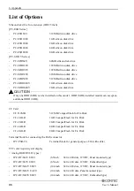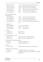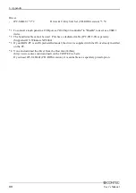
5. Each Component Function
80
User’s Manual
Reset Switch
The BOX-PC is equipped with a hardware reset switch. To prevent it from being pressed by mistake, the
switch is designed to be difficult to press. Use a pointed object to push the switch with.
IDE Interface
Connector for the Internal Drive (Primary IDE Connector)
The module is equipped with an E-IDE controller, allowing a 2.5-inch IDE hard disk drive to the on-
board connector using the bundled hard disk bracket.
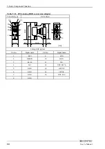
Table 5.20. Primary IDE Connector
Pin No.
1
3
5
7
9
11
13
15
17
19
21
23
25
27
29
31
33
35
37
39
41
43
RESET-
Signal
DD7
DD6
DD5
DD4
DD3
DD2
DD1
DD0
GND
DDRQ
DIOW-
DIOR-
IOCHRDY
DDACK-
INTRQ
DA1
DA0
CSI-
DACT-
+5V
GND
I/
Direction
Output
I/O
O
I/O
I/O
I/O
I/O
I/O
I/O
-------
Input
Output
Output
Input
Output
Input
Output
Output
Output
Output
-------
-------
40
42
44
2
4
6
8
Pin No.
10
12
14
16
18
20
22
24
26
28
30
32
34
36
38
Signal
GND
DD8
DD10
DD9
DD11
DD12
DD13
DD14
DD15
N.C.
GND
GND
GND
DALE
GND
N.C.
N.C.
DA2
CS3-
GND
+5V
N.C.
-------
I/O
I/O
I/O
I/O
I/O
I/O
I/O
I/O
-------
-------
-------
-------
Output
-------
Direction
-------
Output
Output
-------
-------
-------
Connector in use
44-socket header type (2mm pitch)
43
44
1
2

