3. Hardware Setup
User’s Manual
13
Locations and Settings of Internal Connectors and Jumpers
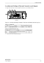
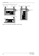
A jumper and connectors are located under the left-side cover as illustrated below.
< Left-side >
HDD
CN1
JP1
CN5
Figure 3.3. Locations and Settings of Jumpers, Connectors, and Switches inside the Top Cover
Table 3.1. Jumper List
Name
Function
Factory setting Reference page
JP1
Sets RS-485 termination
Open
78, 79
Table 3.2. Internal Connector List
Name
Function
Reference page
CN1
CD-ROM Connection Connector (36 pin half pitch)
81
CN5
CF Card Connector *1
82
*1
Insert the CF card with the bottom face down.


