6
1.
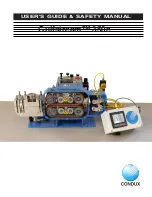
The operating instructions contain a full description of the Gulfstream™ 350e, which
has been designed for the purpose of feeding fiber optic cable through round conduits
of uniform cross section. The conduit must previously have been installed underground
or overhead to receive the fiber optic cable and must be of sufficient length on exit
to be received by the machine. The conduit must be made from HDPE material to
be adequately sealed in the exit of a machine. The conduit must be air tight up to a
pressure of 215 psi (15 bar). For this purpose, connectors of screw, compression or
fusion type must be used. Conduits from (8 mm) to 1.25" (42 mm) and fiber optic cables
from 5/32" (4 mm) to 5/8" (16 mm) diameter can be accepted by the machine.
TRADITIONAL DUCT
Fiber optic cable is fed into the conduit by combining pulling and pushing forces,
which draw the fiber optic cable through the conduit. The pulling force is achieved by
connecting the leading end of the fiber optic cable to a piston or carrier (Figure 76),
which fits exactly into the conduit to make an airtight seal. Air under pressure is fed
in behind the carrier causing it to be forced through the conduit. As the carrier moves
through the conduit (Figure 79), it pulls the fiber optic cable behind it. The fiber optic
cable is continuously pushed into the conduit by a tractor drive. This consists of two
belt drives, which grip the top and bottom of the fiber optic cable moving it into the
conduit (Figure 80). This ensures the fiber optic cable is always free as it moves into the
conduit and reduces the magnitude of the pulling forces needed to carry the leading
end through. Special lubricants are used to make it easier for the carrier to pass through
the conduit.
MICRO DUCT
The fiber optic cable is fed through the duct (Figure 86) by a combined pulling and
pushing force. The pulling force is achieved when pressurized air is fed into the air block
and forced into the duct, generating drag on the fiber cable from airflow passing over it.
The pushing force is created by engaging the tractor drive system. As the tractor drive
feeds fiber cable into the duct, drag force is created by the airflow. The fiber optic cable
floats in the conduit, minimizing any resistance to being pushed in by the tractor drive.
Cable tips (sold separately) may be used to help with transitions. Fiber is pushed out
until speed drops, then air is introduced into the duct in small increments (1-2 bar) at a
time, so as not to pressurize the duct in front of the fiber.
The exit of the machine consists of an air box (Figure 65) that is made in two halves that
clamp together. The air box contains special removable seals (Figure 82) on entry and
exit, which clamp around either the end of the conduit or the fiber optic cable to be
fed into the conduit. The seals can be changed to accommodate different conduit and
fiber optic cable sizes. The conduit is clamped between a pair of seals at the entrance to
the air block. A clamp located in front of the entrance to the air block holds the conduit
mechanically to prevent it from moving axially. The fiber optic cable enters through two
seals located in an aluminum venturi that splits in half. The aluminum venturi is located
in the entrance to the air box and is shaped to ensure an airtight seal around the fiber
optic cable. When the two halves of the air box are closed, air pressure is admitted into
the space between the seals on entry and exit.
GENERAL INFORMATION
Содержание Gulfstream 350e
Страница 1: ...Gulfstream 350e USER S GUIDE SAFETY MANUAL...
Страница 2: ......
Страница 3: ...3...
Страница 17: ...17 Figure 22 Insert USB Figure 23 Copy to USB...
Страница 19: ...19 Figure 26 WIFI On Figure 27 Select GS350 e Enter password Condux145 passwords are case sensitive f Connect...
Страница 50: ...50 Notes...
Страница 51: ...51 Notes...


