background image

Stan dard Fea tures of the Cy ber 4

Sys tem Com po nents

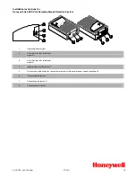
The Cyber 4 installation kit contains the following components:

One Prewired 24-pin connector harness

One Antenna

One Prewired 2-pin connector harness

One High Output Siren

One Cyber 4 Control Unit

One PlainView 2 Coded Valet Switch

One Hardware Kit

One Prewired LED

One Dual Zone Piezo Sensor

One User’s Manual

Two Remote Transmitters

Two Clifford Window Decals

3

n

Lifetime Warranty

n

Two ACG™ 2 Remote Controls

n

Audible Low Remote Battery Warning

n

Built-In Starter or Ignition Immobilizer

n

FACT—False Alarm Control & Test

n

Remote Siren Silencing

n

Dual Zone Piezo Sensor™

n

Dual-Mode “Chirp” Silencing

n

Patented UltraSecure Coded Valet

Mode™

n

Optional DataPort™ Interface to Your

Own PC

n

Point-and-Click Feature Programming 

n

Complete System Diagnostics

At-A-Glance

n

High-Output Siren

n

Remote Door Locking/Unlocking with

built-in relays

n

Remote Panic with Smart

Locking/Unlocking 

n

Built-In Dual Parking Light Flasher

with Onboard Relay

n

Remote Courtesy Lighting

n

Remote Keyless Entry and Accessory

Activation Even in Valet

n

Patented Smart AutoTesting™ 

n

Smart Remote Trunk Release

n

User-Selectable AutoArming

n

User-Selectable AutoArm & Lock

n

Instant AutoArm Bypass

n

Patented Malfunction AutoBypass™

n

Patented SmartPowerUp™ 2

n

MultiVehicle Control with One Remote

n

Eight-Event TotalRecall™

n

Smart Prior Intrusion Attempt Alert

n

Patented Remote Control Code

Learning and MultiRemote Recognition

n

Clear All Remotes

n

LED Status Indicator with Automatic

Battery-Saving Mode

n

SecureAccess™ Programming

n

Pre-Loomed Wiring

n

2 Accessory Outputs with Selectable

Output Type, One with Selectable

AutoActivation for All-Close Windows

n

Integrated Electronic Timer for Remote 

Headlight Activation or Timed Turbo

Cooldown

n

Installer-Selectable Door Ajar/Delayed 

Courtesy Lights

n

Prewired LED, Sensor and PlainView 2

Switch Connectors

Содержание Cyber 4

Страница 1: ......

Страница 2: ...ormation and for wiring diagrams and servicing information on older Clifford products 24 hour AutoFax 1 800 444 4667 24 hour dealer website www clifforddealer com Clifford Electronics Inc n 20750 Lass...

Страница 3: ...ing Lights 9 Auxiliary A with Selectable Output Type 10 Auxiliary B with Selectable Output Type and AutoActivation 10 Window Control 10 Stator or Ignition Immobilization Circuit 11 Engine Compartment...

Страница 4: ...PEAKER WIRE 7 Discuss place ment of the LED valet switch win dow de cals etc with the ve hi cle owner prior to installation 8 DO NOT mount components nor route wires near hot or moving vehicleparts Cl...

Страница 5: ...ote Door Locking Unlocking with built in relays n Remote Panic with Smart Locking Unlocking n Built In Dual Parking Light Flasher with Onboard Relay n Remote Courtesy Lighting n Remote Keyless Entry a...

Страница 6: ...4...

Страница 7: ...oor unlock normally open 24 White Green Door lock comm Passenger Compartment Connections Control Unit and Antenna The Cyber 4 control unit must be installed inside the vehicle Under no circumstances s...

Страница 8: ...terface capabilities and are able to interface with any power door lock configuration including some Mercedes Benz and Audi vehicles that require a 3 second lock pulse pulse duration is installer prog...

Страница 9: ...Unlock Diagram 6 then if 1989 or older program the system for a 3 second lock pulse 6 The Cyber 4 can also provide double lock and unlock pulses or required by some vehicles such as some Nissans Volks...

Страница 10: ...ress into place Dual Zone Piezo Sensor Mount the Dual Zone Piezo Sensor in the passenger compartment not in the engine compartment 1 Firmly mount the sensor near the base of the steering column if the...

Страница 11: ...and find the single wire that shows 12v when the parking lights are on and 0 volts when they are off 4 Connect both of the BROWN wires to the parking light wires Dual Parking Light Circuit Most Europe...

Страница 12: ...s a timed output to close the power windows and sunroof on vehicles that have an all close feature see theWindow Control section at the end of this manual for more information on wiring this feature S...

Страница 13: ...D wire to the starter side of the cut starter line 5 Locate the ignition switch wireloom under the dash and use a voltmeter to locate the one wire that carries 12V throughout BOTH the cranking and eng...

Страница 14: ...special connections or testing are needed simply turn on the Delayed Courtesy Lights feature as noted in theInstaller Programmable Features section on page 16 Please note that since this feature sets...

Страница 15: ...ress remote control button 1 to arm and then again to disarm and then release the button 3 The LED will flash 1 10 times pause then flash 1 10 times etc Write down the number of flashes in each cycle...

Страница 16: ...mming code of 2 by pressing the PlainView 2 Switch s button twice then press the unmarked button 4 After entering the code press and hold the for about 3 seconds until you hear one siren chirp and the...

Страница 17: ...AutoUnlock Off On Clear All Remotes NOTE 4 NOT USED Window Rolldown Vent with Secondary Remote Requires SmartWindows 4 NOTE 6 7 Reset All to Factory Settings except remotes and valet code NOTE 3 Valet...

Страница 18: ...ocedure as on page 15 but after completing step 4 continue to press and hold the side of the PlainView 2 Switch for another 10 seconds You ll hear 3 chirps to indicate the system is in installer progr...

Страница 19: ...to the true ignition line instead of a 12V or accessory line and verify that the transmitters are programmed correctly Step 3 Test the chirps Close all doors and arm the Cy ber 4 by pressing the butto...

Страница 20: ...esystemdisarmed remotedisarmingis ac knowl edged with one chirp and one parking light flash Disarm and rearm the system nNo flashes If no flashes ver ify the parking light bulbs are op era tional If n...

Страница 21: ...round circuit If both wires test correctly then the valet code has been changed Use the CliffNet Wizard Pro to reset the valet code Step 8 Test the Dual Zone Piezo Sensor Arm the system and tap the ca...

Страница 22: ...an 1 5 volts Also make sure the trunk pin switch is connected to the correct wire If not the trunk pin switch must be thor oughly cleaned or re placed or polarity may need to be inverted Step 12 Test...

Страница 23: ...d window decals to the vehicle s windows after discussing placement with the vehicle owner Step 16 Demonstrate Basic System Operation Remote control operation nArming disarming and locking unlocking n...

Страница 24: ......

Отзывы: