-6-
6.4 Valet/Override Switch
Prior to drilling the hole for the valet switch, make sure the switch is well hidden and
can't be easily hit. Also, verify there is adequate space behind the valet switch to
accommodate for the depth of the switch.
6.5 Status LED
Mount the status LED so that it is visible from both sides of the vehicle, if possible.
Make sure there is adequate space behind the LED to accommodate for the depth
of the LED.
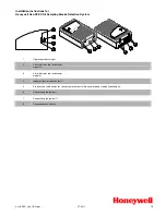
7. Remote Transmitter Layout
Auxiliary 1/
Auxiliary 2 w/
shift
Arm/Lock
Disarm/Unlock
Level Shift
Start
MS2107 install.qxd 8/25/2003 12:50 PM Page 6
Содержание UNGO MS2105
Страница 18: ... 18 18 Dome Light Supervision Relay Diagrams Negative Door Pinswitch Positive Door Pinswitch ...
Страница 19: ... 19 19 Trunk Hatch Release Diagrams Negative Trunk Release Wire Positive Trunk Release Wire ...
Страница 21: ...Positive Door Lock System 21 22 Door Lock Diagrams Negative Door Lock System ...
Страница 22: ... 22 Reverse Polarity Door Lock System ...
Страница 23: ... 23 Actuator Diagram ...
Страница 24: ... 24 Vacuum Pump System ...
Страница 25: ... 25 Negative Door Lock System with Driver s Door Priority 23 Driver s Door Priority Wiring Diagrams ...
Страница 26: ... 26 Positive Door Lock System with Driver s Door Priority ...
Страница 27: ... 27 Reverse Polarity Door Lock System with Driver s Door Priority ...


