Contents
Page 65
4.3.9
Onboard Battery
The system uses non-volatile memory to retain system information when system
power is removed. This memory is powered by a lithium battery on the PCH board. In
addition, the system also uses a super charged capacitor.
4.3.9.1
Replacing the Battery
1.
Begin by removing power from the system.
2.
Rotate the black thumb screw counterclockwise in order to pull out the lever.
3.
Use the lever to pull the PCH module out of the chassis.
4.
Push aside the small clamp that covers the edge of the battery. When the battery
is released, lift it out of the holder.
5.
To insert a new battery, slide one edge under the lip of the holder with the
positive (+) side facing up. Then push the other side down until the clamp snaps
over it.
6.
Insert the PCH module back to the chassis and fully close the lever before locking
it by rotating the red, black thumb screw clockwise.
Note:
Handle used batteries carefully. Do not damage the battery in any way; a
damaged battery may release hazardous materials into the environment. Do not
discard a used battery in the garbage or a public landfill. Comply with the regulations
set up by your local hazardous waste management agency to dispose of your used
battery properly.
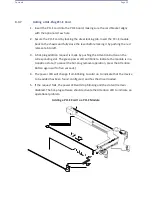
LITHIUM BATTERY
BATTERY HOLDER
Installing the Onboard Battery
Warning:
There is a danger of explosion if the onboard battery is installed upside down
(which reverses its polarities). The battery must be replaced only with the same or an
equivalent type recommended by the manufacturer (CR2032).
Содержание UCS C890 M5
Страница 15: ...Contents Page 15 Location of the C890 M5 BMC Card ...
Страница 19: ...Contents Page 19 Five 5 C890 M5 PCIEBOARD on the Rear side of Midplane ...
Страница 25: ...Contents Page 25 C890 M5 BPLANE Midplane Layout Rear Side ...
Страница 26: ...Contents Page 26 Front View of the C890 M5 BPLANE Midplane ...
Страница 27: ...Contents Page 27 Rear View of the C890 M5 BPLANE Midplane ...
Страница 28: ...Contents Page 29 2 3 14 Location of the C890 M5 BPLANE Midplane The CPU Board ...
Страница 33: ...Contents Page 34 2 6 1 System Block Diagram This section provides a detailed block diagram of the system ...
Страница 44: ...Contents Page 46 ...
Страница 48: ...Contents Page 50 Mixed DIMM DC PMem Population Table ...
Страница 55: ...Contents Page 57 6 Pull the card out of the PCI E board Removing a PCI E Module 3 4 ...
Страница 56: ...Contents Page 58 Removing a PCI E Card from a PCIE Module 5 6 ...
Страница 59: ...Contents Page 61 Installing a PCI E Card in a CPU Module ...
Страница 60: ...Contents Page 62 Installing a PCI E Card in a CPU Module cont ...
Страница 62: ...Contents Page 64 Installing a PCI E Card in a Storage Module ...
Страница 64: ...Contents Page 66 Installing the Battery 3 2 ...
Страница 66: ...Contents Page 68 Mounting a Drive in a Carrier ...
Страница 70: ...Contents Page 72 Removing the Storage Module Cover ...
Страница 71: ...Contents Page 73 Installing Removing 2 5 HDDs with bracket ...
Страница 86: ...90 Contents Page 90 ...
Страница 90: ...95 Contents Page 95 ...
Страница 162: ...Contents Page 167 Change the Option ROM setting to EFI Press ESC to return to return to the main screen ...
Страница 163: ...Contents Page 168 Save changes and Reset ...
Страница 165: ...Contents Page 170 ...
Страница 167: ...Contents Page 172 ...
Страница 168: ...Contents Page 173 ...
Страница 169: ...Contents Page 174 Emulex FC ...
Страница 171: ...Contents Page 176 ...
Страница 177: ...BIOS PCIe Configuration Page 182 Change the Option ROM setting to EFI Press ESC to return to the main screen ...
Страница 178: ...BIOS PCIe Configuration Page 183 Save changes and Reset ...
Страница 179: ...BIOS PCIe Configuration Page 184 Confirm by selecting yes ...
Страница 182: ...BIOS PCIe Configuration Page 187 ...
Страница 183: ...BIOS PCIe Configuration Page 188 ...
Страница 184: ...BIOS PCIe Configuration Page 189 ...
Страница 185: ...BIOS PCIe Configuration Page 190 ...
Страница 186: ...BIOS PCIe Configuration Page 191 ...
Страница 187: ...BIOS PCIe Configuration Page 192 Another default setting is in regards the network stack in the PCIE section ...
Страница 188: ...BIOS PCIe Configuration Page 193 Default is enabled ...
Страница 190: ...BIOS PCIe Configuration Page 195 ...
Страница 191: ...BIOS PCIe Configuration Page 196 ...

