Contents
Page 51
Legend
DDR4 Type
Capacity
DRAM1
RDIMM
3DS
LRDIMM
3DS
Refer to Validation
Matrix (DDR4 DIMMs
validated with DCPMM)
on the next page.
RDIMM
LRDIMM
DRAM2
RDIMM
-
-
DRAM3
RDIMM
3DS
LRDIMM
-
RDIMM
Note
: DDR4 single rank DIMMs based on x8 devices are not compatible with any DCPMM
operating mode.
Legend
Capacity
DCPMM
Any Capacity (Uniformly for all channels for a given configuration)
1.
For MM, general NM/FM ratio is between 1:4 and 1:16. Excessive capacity for FM can
be used for AD. (NM = Near Memory; FM = Far Memory)
2.
For each individual population, rearrangements between channels are allowed as long
as the resulting population is compliant with the X11 memory population rules for the
2nd Gen Intel® Xeon® Platinum 82XX processors.
3.
For each individual population, use the same DDR4 DIMM in all slots.
4.
For each individual population, sockets are normally symmetric with exceptions for 1
DCPMM per socket and 1 DCPMM per node case.
5.
No mixing of DCPMM and NVMDIMMs within the same platform is allowed.
6.
This DCPMM population guide targets a balanced DCPMM-to-DRAM-cache ratio in MM
and MM + AD modes.
Содержание UCS C890 M5
Страница 15: ...Contents Page 15 Location of the C890 M5 BMC Card ...
Страница 19: ...Contents Page 19 Five 5 C890 M5 PCIEBOARD on the Rear side of Midplane ...
Страница 25: ...Contents Page 25 C890 M5 BPLANE Midplane Layout Rear Side ...
Страница 26: ...Contents Page 26 Front View of the C890 M5 BPLANE Midplane ...
Страница 27: ...Contents Page 27 Rear View of the C890 M5 BPLANE Midplane ...
Страница 28: ...Contents Page 29 2 3 14 Location of the C890 M5 BPLANE Midplane The CPU Board ...
Страница 33: ...Contents Page 34 2 6 1 System Block Diagram This section provides a detailed block diagram of the system ...
Страница 44: ...Contents Page 46 ...
Страница 48: ...Contents Page 50 Mixed DIMM DC PMem Population Table ...
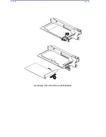
Страница 55: ...Contents Page 57 6 Pull the card out of the PCI E board Removing a PCI E Module 3 4 ...
Страница 56: ...Contents Page 58 Removing a PCI E Card from a PCIE Module 5 6 ...
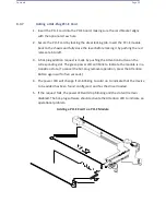
Страница 59: ...Contents Page 61 Installing a PCI E Card in a CPU Module ...
Страница 60: ...Contents Page 62 Installing a PCI E Card in a CPU Module cont ...
Страница 62: ...Contents Page 64 Installing a PCI E Card in a Storage Module ...
Страница 64: ...Contents Page 66 Installing the Battery 3 2 ...
Страница 66: ...Contents Page 68 Mounting a Drive in a Carrier ...
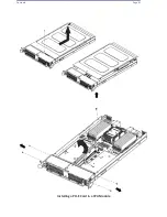
Страница 70: ...Contents Page 72 Removing the Storage Module Cover ...
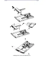
Страница 71: ...Contents Page 73 Installing Removing 2 5 HDDs with bracket ...
Страница 86: ...90 Contents Page 90 ...
Страница 90: ...95 Contents Page 95 ...
Страница 162: ...Contents Page 167 Change the Option ROM setting to EFI Press ESC to return to return to the main screen ...
Страница 163: ...Contents Page 168 Save changes and Reset ...
Страница 165: ...Contents Page 170 ...
Страница 167: ...Contents Page 172 ...
Страница 168: ...Contents Page 173 ...
Страница 169: ...Contents Page 174 Emulex FC ...
Страница 171: ...Contents Page 176 ...
Страница 177: ...BIOS PCIe Configuration Page 182 Change the Option ROM setting to EFI Press ESC to return to the main screen ...
Страница 178: ...BIOS PCIe Configuration Page 183 Save changes and Reset ...
Страница 179: ...BIOS PCIe Configuration Page 184 Confirm by selecting yes ...
Страница 182: ...BIOS PCIe Configuration Page 187 ...
Страница 183: ...BIOS PCIe Configuration Page 188 ...
Страница 184: ...BIOS PCIe Configuration Page 189 ...
Страница 185: ...BIOS PCIe Configuration Page 190 ...
Страница 186: ...BIOS PCIe Configuration Page 191 ...
Страница 187: ...BIOS PCIe Configuration Page 192 Another default setting is in regards the network stack in the PCIE section ...
Страница 188: ...BIOS PCIe Configuration Page 193 Default is enabled ...
Страница 190: ...BIOS PCIe Configuration Page 195 ...
Страница 191: ...BIOS PCIe Configuration Page 196 ...


