Contents
Page 35
3
Server Installation
3.1
Overview
This chapter provides advice and instructions for mounting your system in a server
rack. If your system is not already fully integrated with processors, and system
memory.
Caution:
Electrostatic Discharge (ESD) can damage electronic components. To prevent
such damage to PCBs (printed circuit boards), it is important to use a grounded wrist
strap, handle all PCBs by their edges and keep them in anti-static bags when not in
use.
3.2
Preparing for Setup
The box in which the system was shipped should include the rackmount hardware
needed to install it into the rack.
3.3
Choosing a Setup Location
•
The system should be situated in a clean, dust-free area that is well ventilated.
Avoid area where heat, electrical noise and electromagnetic fields are
generated.
•
Leave enough clearance in front of the rack so that you can open the front
door completely (~25 inches) and approximately 30 inches of clearance in the
back of the rack to allow sufficient space for airflow and access when
servicing.
•
This product should be installed only in a Restricted Access Location (dedicated
equipment rooms, service closets, etc.).
•
This product is not suitable for use with visual display workplace devices
according to §2 of the German Ordinance for Work with Visual Display Units.
3.4
Rack Precautions
•
Ensure that the leveling jacks on the bottom of the rack are extended to the
floor so that the full weight of the rack rests on them.
•
In single rack installations, stabilizers should be attached to the rack. In
multiple rack installations, the racks should be coupled together.
Содержание UCS C890 M5
Страница 15: ...Contents Page 15 Location of the C890 M5 BMC Card ...
Страница 19: ...Contents Page 19 Five 5 C890 M5 PCIEBOARD on the Rear side of Midplane ...
Страница 25: ...Contents Page 25 C890 M5 BPLANE Midplane Layout Rear Side ...
Страница 26: ...Contents Page 26 Front View of the C890 M5 BPLANE Midplane ...
Страница 27: ...Contents Page 27 Rear View of the C890 M5 BPLANE Midplane ...
Страница 28: ...Contents Page 29 2 3 14 Location of the C890 M5 BPLANE Midplane The CPU Board ...
Страница 33: ...Contents Page 34 2 6 1 System Block Diagram This section provides a detailed block diagram of the system ...
Страница 44: ...Contents Page 46 ...
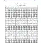
Страница 48: ...Contents Page 50 Mixed DIMM DC PMem Population Table ...
Страница 55: ...Contents Page 57 6 Pull the card out of the PCI E board Removing a PCI E Module 3 4 ...
Страница 56: ...Contents Page 58 Removing a PCI E Card from a PCIE Module 5 6 ...
Страница 59: ...Contents Page 61 Installing a PCI E Card in a CPU Module ...
Страница 60: ...Contents Page 62 Installing a PCI E Card in a CPU Module cont ...
Страница 62: ...Contents Page 64 Installing a PCI E Card in a Storage Module ...
Страница 64: ...Contents Page 66 Installing the Battery 3 2 ...
Страница 66: ...Contents Page 68 Mounting a Drive in a Carrier ...
Страница 70: ...Contents Page 72 Removing the Storage Module Cover ...
Страница 71: ...Contents Page 73 Installing Removing 2 5 HDDs with bracket ...
Страница 86: ...90 Contents Page 90 ...
Страница 90: ...95 Contents Page 95 ...
Страница 162: ...Contents Page 167 Change the Option ROM setting to EFI Press ESC to return to return to the main screen ...
Страница 163: ...Contents Page 168 Save changes and Reset ...
Страница 165: ...Contents Page 170 ...
Страница 167: ...Contents Page 172 ...
Страница 168: ...Contents Page 173 ...
Страница 169: ...Contents Page 174 Emulex FC ...
Страница 171: ...Contents Page 176 ...
Страница 177: ...BIOS PCIe Configuration Page 182 Change the Option ROM setting to EFI Press ESC to return to the main screen ...
Страница 178: ...BIOS PCIe Configuration Page 183 Save changes and Reset ...
Страница 179: ...BIOS PCIe Configuration Page 184 Confirm by selecting yes ...
Страница 182: ...BIOS PCIe Configuration Page 187 ...
Страница 183: ...BIOS PCIe Configuration Page 188 ...
Страница 184: ...BIOS PCIe Configuration Page 189 ...
Страница 185: ...BIOS PCIe Configuration Page 190 ...
Страница 186: ...BIOS PCIe Configuration Page 191 ...
Страница 187: ...BIOS PCIe Configuration Page 192 Another default setting is in regards the network stack in the PCIE section ...
Страница 188: ...BIOS PCIe Configuration Page 193 Default is enabled ...
Страница 190: ...BIOS PCIe Configuration Page 195 ...
Страница 191: ...BIOS PCIe Configuration Page 196 ...


