18
Plus 42 - 45 - 50 - 55 - 55S - 55E
11-2000
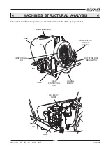
T2. RETURN TO TANK PIPING
It connects tap P6 to tank P1, at the point on which the hydraulic shaker is mounted.
P7. 2-WAY LEVER FILLING TAP
It is mounted on pump P4 and connected to tank P1 through the filler piping T3.
T3
c
a
P7
a = OPEN
when the control lever is parallel at the
tap’s body
c = CLOSED
when the lever is perpendicular
to the tap.
It must normally remain in the closed
position.
It is only opened to carry out the
loading of the tank through the filler
piping (see point 8.3).
When the operation is complete, it
must be returned to the closed posi-
00138
tion.
T3. PIPING FOR THE LOADING
It connects tap P7 to tank P1 for the filling.
P8. SELF-CLEANING IN-LINE DELIVERY FILTER
It is mounted on tap P5 and connected to the distributor (P10/E10) through the feed piping (T6).
A ring nut locks the lid to the filter body. The self-cleaning and mixing tap is set below the lid and is fitted
with a control knob:
— OPEN (anticlockwise rotation) the tap to
carry out the draining or the mixing of powder
products;
— CLOSE (clockwise rotation) the tap in order
that the operations are not carried out.
Filter (filtering capacity of 250 lt/min.), with a 50-
mesh cartridge.
A soiled cartridge determines a lowering of the
operating pressure.
This malfunction is signalled by the relevant
gauge.
This machine device only filters the feed flow to
the heads, considerably reducing the chances
of cartridge clogging.
P8
c
a
T4
T6
P9
T5
00024

