


15
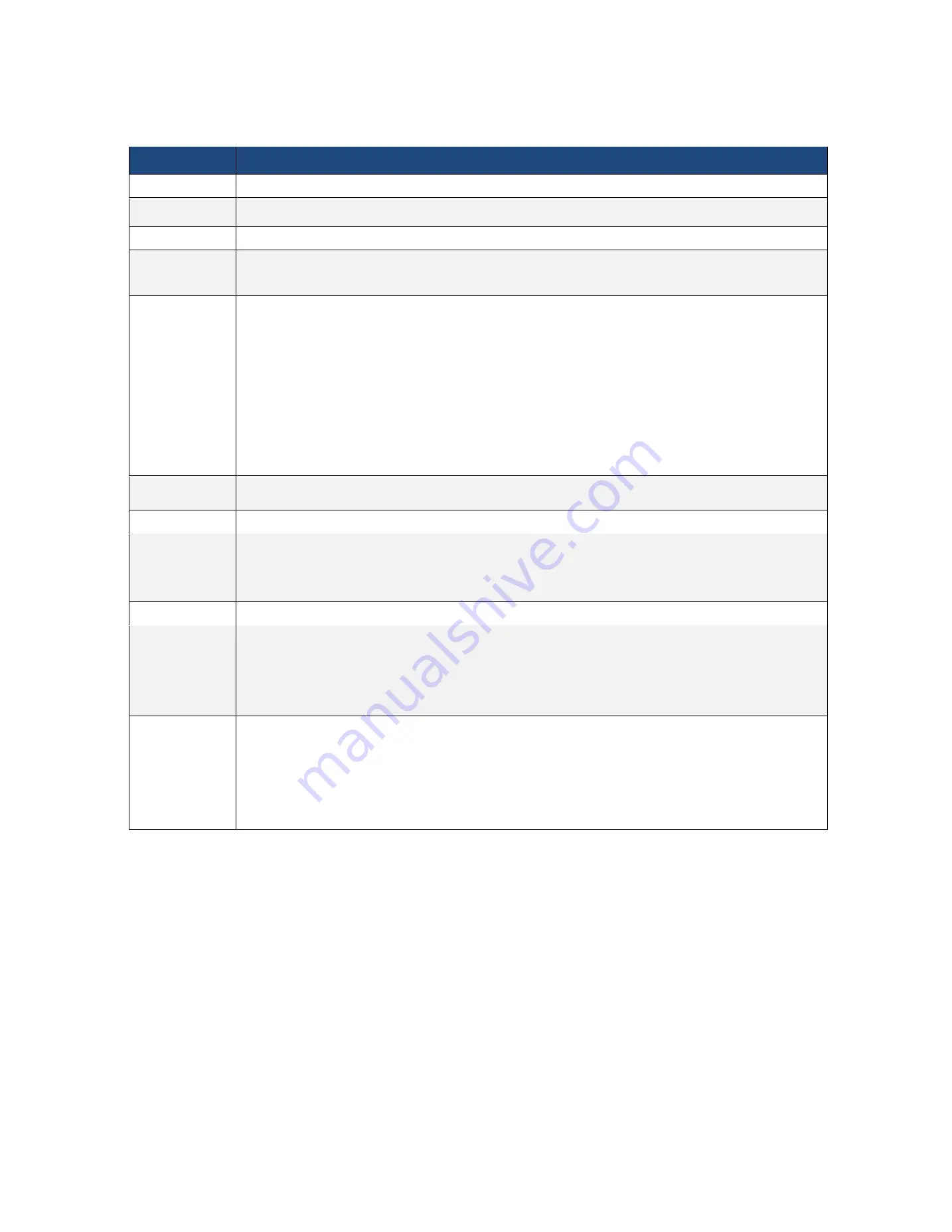
Feature
Specification
Form factor
mATX
Processor Support
Support Intel® 10th Gen. Core™ i9/i7/i5/i3, Pentium, Celeron® Series Processors
Chipset
Intel® Z490
Memory
4 x 288-pin DDR4 DIMM slots
Support up to 128GB DDR4 non-ECC UDIMM
LAN
2 x RJ45 GLAN by Intel® i210
2 x RJ45 10G base-T by Intel® X710-AT2
1 x RJ45 Dedicated IPMI LAN port by RTL8211E
Supports Wake-On-LAN
Supports Energy Efficient Ethernet 802.3az
Supports Dual LAN with Teaming function
Supports PXE
LAN1 supports NCSI
VGA / VRAM
Integrated in BMC with DDR4 256MB VRAM
BMC
ASPEED AST2500
Expansion Slot
Slot 6: Gen3 x16 link, auto switch to x8 link if Slot 4 is occupied (Physical x16, EE x16/x8 (from CPU), shared with Slot 4)
Slot 4: Gen3 x8 link (Physical x8, EE x0/x8 (from CPU), shared with Slot 6)
Slot 7: Gen3 x1 link (Physical x1, EEx1 (from PCH))
Storage
6 x SATA3 6Gb/s (SATA0-5, SATA_0 supports SATA DOM)
Rear IO Connector
1x HDMI Port, 1x VGA Port, 1x Serial Port, 1x UID
2x USB 3.2 Gen1 Type-A (5Gbps), 2x USB 3.2 Gen2 Type-A (10Gbps)
4 +1 RJ45 Gigabit Ethernet LAN ports
LAN Ports with LED (ACT/LINK LED and SPEED LED)
Internal Connector
ATX Power 1x (24-pin) + 1x (8-pin) + 1x (4-pin)
Front Panel Connector 1x (RST, PWRBTN, HDDLED, PWRLED)
Fan Header 7x (1CPU/4Front/2Rear)
USB 3.2 Gen1 Header 1x (supports 2 USB 3.1 Gen1 ports)
USB 2.0 Header 1x (supports 2 USB 2.0 ports)
Содержание ORION HF210-G5
Страница 1: ...ORION HF210 G5 User Manual...
Страница 13: ...12 8 4 Support and Certification Labels...
Страница 14: ...13 9 Chassis Layout The following illusration shows inside of the ORION HF210 G5 system...
Страница 15: ...14 10 Motherboard Layout The following picture shows the motherboard layout in the ORION HF210 G5 system...
Страница 19: ...18 11 2 Jumper Functionality...
Страница 20: ...19...
Страница 22: ...21 11 4 Block Diagram...
Страница 31: ...30 Step 3 Twist the card and remove from chassis...
Страница 32: ...31 Step 4 Put another PCIe card in and install into the slot Step 5 Rotate and close the PCIe release latch...
Страница 34: ...33 Step 3 Put another PCIe card in and install into the slot Step 4 Rotate and close the PCIe release latch...
Страница 37: ...36...
Страница 39: ...38 Step 3 Turn over the cage and unscrew 4 screws Step 4 Replace the SSD...
Страница 44: ...43 Step 9 Rotate and close the PCIe release latch...
Страница 57: ...56 Step 3 When main menu of BMC appears then click on the Settings Step 4 Select the Network Settings...
Страница 68: ...67 FRU File ID Product Extra...
Страница 71: ...70 28 7 Settings This group of pages allows you to access various configuration settings Settings Page...
Страница 104: ...103 28 7 14 Video Recording This page is used to configure video recording settings Video Recording Page...
Страница 121: ...120 Step 7 Click on ADVANCED Step 8 Click on Proceed to unsafe Step 9 Enter a Username admin and Password admin...
Страница 124: ...123 Step 14 Click on OK Step 15 Wait until the Processing Window completes...
Страница 125: ...124 Step 16 Click on Proceed Step 17 Click on OK to proceed the BIOS update...
Страница 126: ...125 Step 18 Wait until the BIOS update completes and then click on OK...


