


134
32.2.2 Turbostat
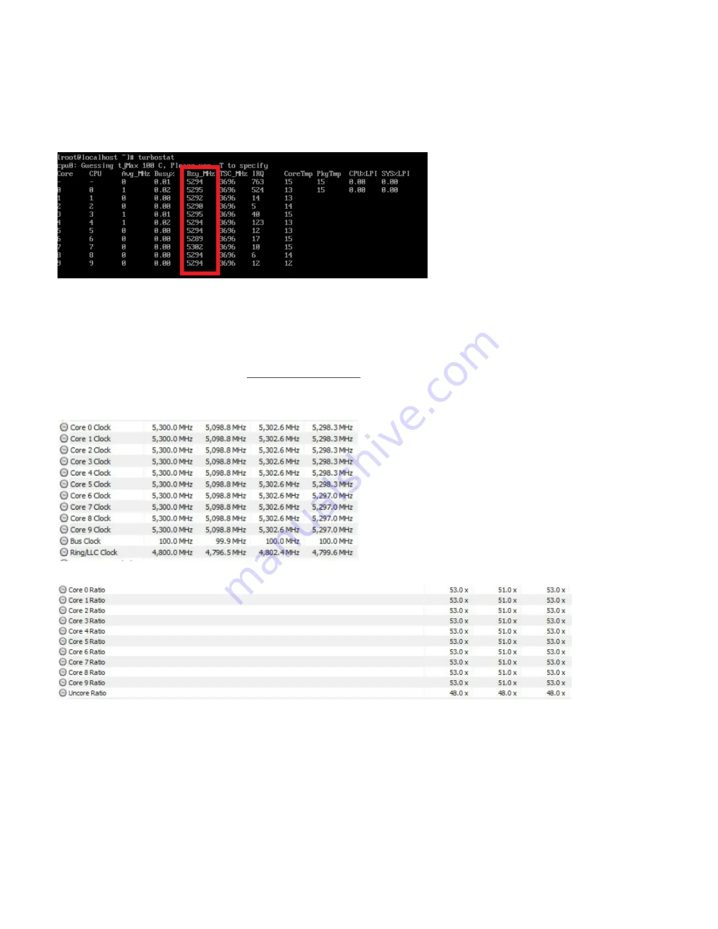
The
turbostat
is the base install utility in the linux and in case it is not possible to install or use
i7z
then run you can run
turbostat
and verify
Bzy_Mhz
for an actual frequency.
32.3 Verifying CPU Frequency for Windows
This sections contains the information how to download and monitor CPU frequencies in the Windows through
HWiNFO64
utility.
The Hwinfo64 utility for Windows available on website: https://www.hwinfo.com/download/
Run the
HWiNFO64
, verify the
appropriate
Core # Clock
and
Core # Ratio
(depending on overclocking profiles).
Содержание ORION HF210-G5
Страница 1: ...ORION HF210 G5 User Manual...
Страница 13: ...12 8 4 Support and Certification Labels...
Страница 14: ...13 9 Chassis Layout The following illusration shows inside of the ORION HF210 G5 system...
Страница 15: ...14 10 Motherboard Layout The following picture shows the motherboard layout in the ORION HF210 G5 system...
Страница 19: ...18 11 2 Jumper Functionality...
Страница 20: ...19...
Страница 22: ...21 11 4 Block Diagram...
Страница 31: ...30 Step 3 Twist the card and remove from chassis...
Страница 32: ...31 Step 4 Put another PCIe card in and install into the slot Step 5 Rotate and close the PCIe release latch...
Страница 34: ...33 Step 3 Put another PCIe card in and install into the slot Step 4 Rotate and close the PCIe release latch...
Страница 37: ...36...
Страница 39: ...38 Step 3 Turn over the cage and unscrew 4 screws Step 4 Replace the SSD...
Страница 44: ...43 Step 9 Rotate and close the PCIe release latch...
Страница 57: ...56 Step 3 When main menu of BMC appears then click on the Settings Step 4 Select the Network Settings...
Страница 68: ...67 FRU File ID Product Extra...
Страница 71: ...70 28 7 Settings This group of pages allows you to access various configuration settings Settings Page...
Страница 104: ...103 28 7 14 Video Recording This page is used to configure video recording settings Video Recording Page...
Страница 121: ...120 Step 7 Click on ADVANCED Step 8 Click on Proceed to unsafe Step 9 Enter a Username admin and Password admin...
Страница 124: ...123 Step 14 Click on OK Step 15 Wait until the Processing Window completes...
Страница 125: ...124 Step 16 Click on Proceed Step 17 Click on OK to proceed the BIOS update...
Страница 126: ...125 Step 18 Wait until the BIOS update completes and then click on OK...


