-
22
-
4. CONNECTIONS
4.4 Measuring Input Terminals
(1) Connection of Measuring Input Terminals
Make sure to turn off the power source before connection for
preventing an electric shock.
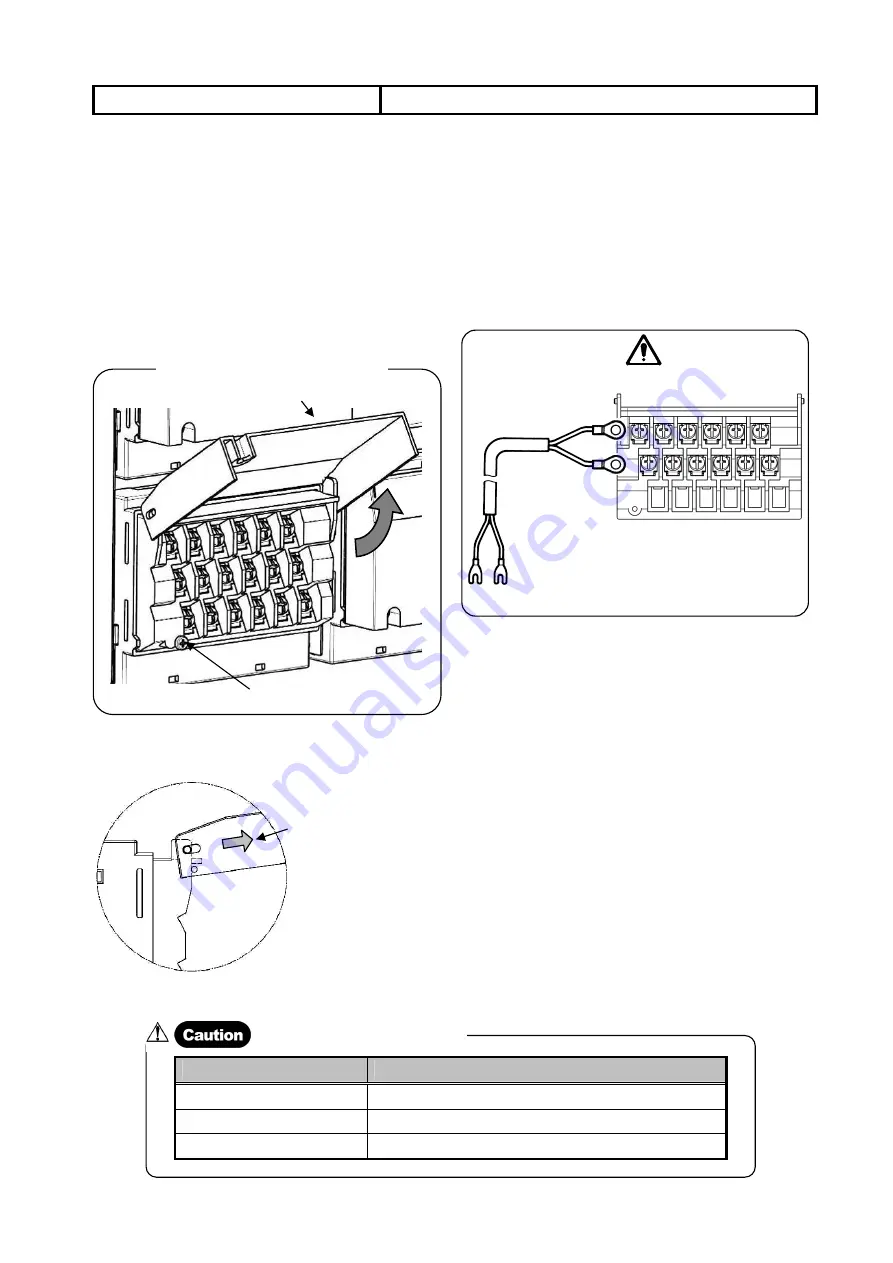
1. Loosen the fixing screw of the input terminals cover and slide the
cover up.
2. Open up the input terminals cover slightly (the cover is removed
from fixing screw) and slide back down (prior to the slide up
position).
3. In the state of slid down position, open the cover up until it stops
(Figure below).
4. The input terminals cover stops at middle position easily (Refer to
figure below: side view).
5. For this connection, use a cable with a crimp style terminal with
an insulation sleeve for the input terminal.
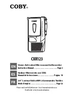
(2) Connection of DC Voltage (Current) Input
Use a twisted cable for instrumentation as the input cable for
suppressing noises.
For the current input (optional), mount a shunt resistor for current
input (Refer to 8.1 Shunt Resister for Current Input) to the channel
to be measured before connections.
Avoid using this instrument in parallel with other instruments,
otherwise troubles may occur (Indication fluctuation, indication
errors, and others may occur.).
DC voltage input
z
DC voltage (current) input
Channel
1
2
3
4
5
6
Twisted cable for
instrumentation
(-)
(+)
State of Input Terminals Cover Opened
Fixing screw
Input terminals cover
The input terminals cover
stops easily when slided to
the direction of an arrow.
Input type
Permissible input voltage
Voltage and thermocouple input
±10VDC or less (Input scale of ±5V or less)
Voltage-divided input
±60VDC or less (Input scale of exceeding ±5V)
Resistance thermometer input
±6VDC or less
Maximum Permissible Input Voltage
Содержание EH3000 Series
Страница 1: ...INST No INE 866 Instruction Manual EH3000 series DOT PRINTING TYPE PEN TYPE 180 mm ANALOG RECORDER ...
Страница 2: ......
Страница 95: ......


