


ENGLISH
.
Cod. 9828093300 00 - Vers. 04/2019 - 3
1.0 GENERAL CHARACTERISTICS
The compressor units use single stage oil-injected rotary screw air compressors.
The unit includes:
compressor; oil separator; oil cooler and output air cooler; fan; electric starter; safety and regulation devices, instrument panel.
The system is self-supporting and does not require any bolts or floor anchoring devices.
The unit is completely factory assembled; the connections necessary for its operation are:
•
connection to mains power: (see installation chapter)
•
connection to compressed air network: (see installation chapter)
The compressor-motor unit is mounted on the frame of the machine by means of elastic supports: this allows the compressor unit to be
rested directly on the floor without the need for any additional anti-vibration elements.
2.0 INTENDED USE
The compressor unit has been developed to supply compressed air for industrial use.
In any case, the machine cannot be used in
places with an explosion or fire hazard, that is, in places where works are performed that release hazardous substances posing a
risk to safety into the environment (for example: solvents, flammable vapours, alcohols, etc. ...).
In particular, the equipment cannot
be used to produce air intended for human respiration or used in direct contact with food substances. These uses are allowed if the
compressed air is treated using a suitable filtration system. (Consult with the manufacturer for these special uses).
This equipment must be used only in accordance with the use for which it was expressly designed.
All other uses shall be considered improper and therefore unreasonable. The Manufacturer shall not be held liable for any damage caused
by improper, erroneous and unreasonable uses.
3.0 OPERATING PRINCIPLE
3.1 OPERATING PRINCIPLE OF SCREW COMPRESSOR
The electric motor and compressor unit are coupled by means of a gear transmission / elastic coupling. The compressor unit withdraws air
from the outside through the intake valve. The withdrawn air is filtered by the filter cartridge installed upstream of the intake valve. Inside the
compressor unit, the air and lubricating oil are compressed and sent to the oil separator, where the oil is separated from the compressed
air; the latter is filtered again by the oil separator cartridge to reduce the suspended oil particles to a minimum. At this point the two flows (of
oil and air) are sent to two distinct coolers where they are cooled, using an air flow withdrawn from the outside using a special fan inside the
machine. The cooled oil is then recirculated while the compressed air is sent to the tank.
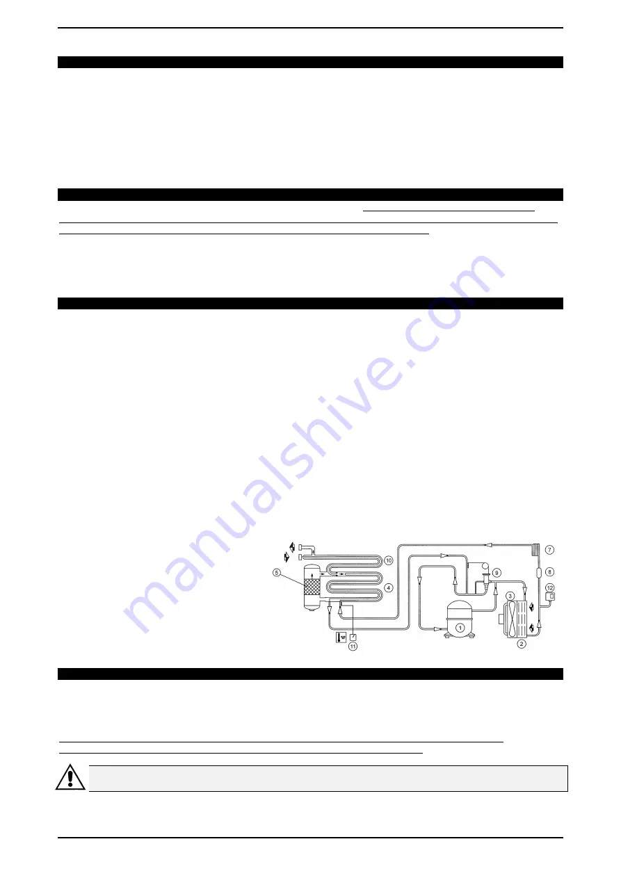
3.2 OPERATING PRINCIPLE OF DRYER
The dryer works as described below. The gaseous coolant coming from the evaporator (4) is withdrawn by the refrigeration compressor (1)
and pumped into the capacitor (2). The latter allows its condensation, eventually assisted by the fan (3); the condensed coolant passes
through the filter drier (8), expands through the capillary tube (7) and returns to the evaporator where it produces the refrigeration effect. By
way of the heat exchange with the compressed air flowing upstream through the evaporator, the coolant vaporises and returns to the
compressor to start a new cycle. The circuit is completed by a coolant bypass system, which intervenes to adapt the available cooling
power to the effective thermal load.
It is developed through the injection of hot gas, controlled by the valve (9): this valve keeps the coolant pressure in the evaporator constant,
and therefore also the dew point, which never falls below 0 °C (32 °F) in order to prevent the condensate from freezing inside the
evaporator
The dryer works in a completely automated manner; it is factory calibrated for a dew point of 5 °C (41 °F) and no further calibration is
required.
DRYER FLOW DIAGRAM.
4.0 GENERAL SAFETY REGULATIONS
Use of the equipment is allowed only by properly trained and authorised personnel.
All and any tampering with or modifications to the equipment not previously authorised by the Manufacturer shall release the latter from all
liability for any damage resulting from or attributable to the aforementioned actions. The removal of or tampering with safety devices
constitutes violation of European Safety Standards
ATTENTION: A DISCONNECT SWITCH WITH AUTOMATIC OVERCURRENT PROTECTION DEVICE, EQUIPPED WITH
DIFFERENTIAL DEVICE MUST BE INSTALLED; SEE WIRING DIAGRAMS FOR CALIBRATIONS.
ALL OPERATIONS ON THE ELECTRICAL SYSTEM, EVEN IF MINOR, MUST BE PERFORMED BY PROFESSIONALLY
QUALIFIED PERSONNEL.
AIR OUTLET
AIR INLET