HEATER A N D AIR C O N D I T I O N I N G
1A-47
vacuum reduces, it indicates a leak in the system or
gauge connections; locate and repair all leaks.
Charging the System
1. Only after evacuating as above, is system ready for
charging. Note reading on sight glass of charging
cylinder. If it does not contain a sufficient amount
of refrigerant for a full charge, fill to the proper
level.
2. With High and Low Pressure Valves (1 and 2) open,
close Vacuum Control Valve (3), turn off vacuum
pump, open refrigerant control valve (4) and allow
refrigerant to enter system.
NOTE: If the charge will not transfer
completely from the station to the system,
close the high pressure valve at the gauge set,
set the air conditioning controls for cooling,
check that the engine compartment is clear of
obstructions, and start the engine. Compres
sor operation will decrease the low side
pressure in the system.
System is now charged and should be checked as
outlined below:
Checking System Operation
1. Operate system for a maximum of five minutes at
maximum cooling, high blower speed and with
engine operating at 2000 RPM (exhaust should be
vented if inside).
2. When system is stabilized, the pressure gauges on
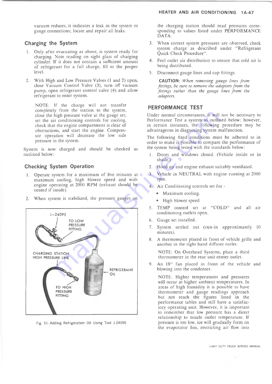
Fig. 51-Adding Refrigeration Oil Using Tool J-24095
the charging station should read pressures corre
sponding to values listed under PERFORMANCE
DATA.
3. When correct system pressures are observed, check
system charge as described under "Refrigerant
Quick Check Procedure".
4. Feel outlet air distribution to ensure that cold air is
being distributed.
5. Disconnect gauge lines and cap fittings.
CAUTIO N:
When removing gauge lines from
fittings, be sure to remove the adapters from the
fittings rather than the gauge lines from the
adapters.
PERFORMANCE TEST
Under normal circumstances, it will not be necessary to
Performance Test a system as outlined below; however,
in certain instances, the following procedure may be
advantageous in diagnosing system malfunction.
The following fixed conditions must be adhered to in
order to make it possible to compare the performance of
the system being tested with the standards below:
1. Doors and windows closed. (Vehicle inside or in
shade.)
2. Hood up and engine exhaust suitably ventilated.
3. Vehicle in NEUTRAL with engine running at 2000
rpm.
4. Air Conditioning controls set for -
• Maximum cooling.
• High blower speed
5. TEMP control set at "COLD" and all air
conditioning outlets open.
6. Gauge set installed.
7. System settled out (run-in approximately 10
minutes).
8. A thermometer placed in front of vehicle grille and
another in the right hand diffuser outlet.
NOTE: On Overhead Systems, place a third
thermometer in the rear unit center outlet.
9. An 18" fan placed in front of the vehicle and
blowing into the condenser.
NOTE: Higher temperatures and pressures
will occur at higher ambient temperatures. In
areas of high humidity it is possible to have
thermometer and gauge readings approach
but not reach the figures listed in the
performance tables and still have a satisfac
tory operating unit. However, it is important
to remember that low pressure has a direct
relationship to nozzle outlet temperature. If
pressure is too low, ice will gradually form on
the evaporator fins, restricting air flow into
J - 2 4 0 9 5
TO LOW
PRESSURE
FITTING
CHARGING STATION
HIGH PRESSURE LINE
REFRIGERANT
OIL
TO HIGH
PRESSURE
FITTING
LIGHT DUTY TRUCK SERVICE MANUAL
Содержание Light Duty Truck 1973
Страница 1: ......
Страница 4: ......
Страница 6: ......
Страница 39: ...HEATER AND AIR CONDITIONING 1A 13 Fig 14 Heater Wiring Diagrams LIGHT DUTY TRUCK SERVICE MANUAL...
Страница 53: ...HEATER AND AIR CONDITIONING 1A 27 LIGHT DUTY TRUCK SERVICE MANUAL...
Страница 115: ...LIGHT DUTY TRUCK SERVICE M A N U A L HEATER AND AIR CONDITIONING 1A 89...
Страница 123: ...BODY 1B 3 Fig 6 Typical 06 Van LIGHT DUTY TRUCK SERVICE MANUAL...
Страница 149: ...BODY 1B 29 Fig 84 Body Mounting 06 Fig 85 Body Mounting 14 LIGHT DUTY TRUCK SERVICE MANUAL...
Страница 171: ...LIGHT DUTY TRUCK SERVICE M A N U A L Fig 2 Frame Horizontal Checking Typical FRAME 2 3...
Страница 173: ...LIGHT DUTY TRUCK SERVICE M A N U A L Fig 4 10 30 Series Truck Frame FRAME 2 5...
Страница 174: ...2 6 FRAME LIGHT DUTY TRUCK SERVICE MANUAL Fig 5 Underbody Reference Points G Van...
Страница 177: ...LIGHT DUTY TRUCK SERVICE MANUAL G 10 20 C 10 P 10 30 Fig 2 Front Suspension C P K Typical FRONT SUSPENSION 3 3...
Страница 185: ...FRONT SUSPENSION 3 11 Fig 16 Toe out on Turns LIGHT DUTY TRUCK SERVICE MANUAL...
Страница 224: ......
Страница 229: ...REAR SUSPENSION AND DRIVELINE 4 5 Fig 13 Rear Spring Installation C K Models LIGHT DUTY TRUCK SERVICE MANUAL...
Страница 266: ......
Страница 310: ...5 44 BRAKES C MODELS G MODELS P MODELS Fig 77 Parking Brake System LIGHT DUTY TRUCK SERVICE MANUAL...
Страница 351: ...ENGINE 6 15 Fig ID Sectional View of Eight Cylinder Engine LIGHT DUTY TRUCK SERVICE MANUAL...
Страница 375: ...EN G IN E 6 39 LIGHT DUTY TRUCK SERVICE MANUAL...
Страница 376: ...6 4 0 ENGINE LIGHT DUTY TRUCK SERVICE MANUAL...
Страница 377: ...ENG IN E 6 41 LIGHT DUTY TRUCK SERVICE MANUAL...
Страница 378: ...LIGHT DUTY TRUCK SERVICE MANUAL Fig 37L K Series Engine Front Mount 6 42 ENG INE...
Страница 379: ...E N G IN E 6 43 FRONT MOUNT REAR MOUNT Fig 38L G Series Engine Mounts LIGHT DUTY TRUCK SERVICE MANUAL...
Страница 400: ...6 6 4 ENG INE LIGHT DUTY TRUCK SERVICE MANUAL...
Страница 401: ...ENG IN E 6 65 LIGHT DUTY TRUCK SERVICE MANUAL...
Страница 402: ...6 6 6 ENGINE LIGHT DUTY TRUCK SERVICE MANUAL...
Страница 403: ...E NG IN E 6 67 Fig 36V C Series Engine Mounts LIGHT DUTY TRUCK SERVICE MANUAL...
Страница 410: ......
Страница 423: ...EN G IN E C OOLING 6K 13 Fig 16 Overheating Chart LIGHT DUTY TRUCK SERVICE MANUAL...
Страница 424: ...6 K 1 4 ENG INE COOLING Fig 17 Coolant Loss Chart LIGHT DUTY TRUCK SERVICE MANUAL...
Страница 455: ...ENGINE FUEL 6M 31 Fig K13 Accelerator Controls P30 42 454 Engine LIGHT DUTY TRUCK SERVICE MANUAL...
Страница 456: ...6M 32 ENGINE FUEL Fig K15 Accelerator Controls G Van L 6 LIGHT DUTY TRUCK SERVICE MANUAL...
Страница 492: ......
Страница 506: ...CEC PLUNGER IS EXTENDED Fig lid Vacuum Advance Diagram Six Cylinder Engine 6T 14 EMISSION CONTROL SYSTEMS...
Страница 512: ...Fig 18e Vacuum Advance Diagram V8 Engine...
Страница 515: ...EMISSION CONTROL SYSTEMS 6T 23 Fig If Six Cylinder A I R System LIGHT DUTY TRUCK SERVICE MANUAL...
Страница 516: ...6 T 2 4 E M IS S IO N CONTROL SYSTEMS LIGHT DUTY TRUCK SERVICE MANUAL...
Страница 517: ...E M IS S IO N C O N TR O L SYSTEM S 6T 25 Fig 4f Diverter Valve Vent Valve LIGHT DUTY TRUCK SERVICE MANUAL...
Страница 528: ......
Страница 540: ...6 Y 1 2 ENGINE ELECTRICAL Fig 16b Battery Installation C K Series LIGHT DUTY TRUCK SERVICE MANUAL...
Страница 572: ...6Y 44 ENGINE ELECTRICAL Fig 25i V 8 Spark Plug Wire Installation LIGHT DUTY TRUCK SERVICE MANUAL...
Страница 590: ......
Страница 592: ...7M 2 CLUTCHES MANUAL TRANSMISSIONS VIEW B Fig la Clutch Linkage Assy C K Models LIGHT DUTY TRUCK SERVICE MANUAL...
Страница 593: ...CLUTCHES MANUAL TRANSMISSIONS 7M 3 LIGHT DUTY TRUCK SERVICE MANUAL...
Страница 594: ...7M 4 CLUTCHES MANUAL TRANSMISSIONS Fig lc Clutch Linkage Assy P Models LIGHT DUTY TRUCK SERVICE MANUAL...
Страница 598: ...7M 8 CLUTCHES MANUAL TRANSMISSIONS LIGHT DUTY TRUCK SERVICE MANUAL...
Страница 642: ......
Страница 654: ......
Страница 656: ...LIGHT DUTY TRUCK SERVICE MANUAL Fig 19M Drive Range Low First Gear Typical 7A 14 AUTOMATIC T R A N S M IS S IO N...
Страница 662: ...LIGHT DUTY TRUCK SERVICE M A N U A L Fig 22M LI Range Manual First Gear Typical 7A 20 AUTOMATIC TRANSMISSION...
Страница 668: ...LIGHT DUTY TRUCK SERVICE M A N U A L Fig 25M Reverse Range Typical 7A 26 AUTOMATIC T R A N S M IS S IO N...
Страница 739: ...FUEL TANKS AND EXHAUST 8 9 Fig 15 Filler Neck and Vent Hose Van LIGHT DUTY TRUCK SERVICE MANUAL...
Страница 740: ...8 10 FUEL TANKS AND EXHAUST Fig 16 Fuel Feed and Return Pipes Front C K LIGHT DUTY TRUCK SERVICE MANUAL...
Страница 743: ...FUEL TANKS AND EXHAUST 8 13 LIGHT DUTY TRUCK SERVICE MANUAL...
Страница 744: ...8 14 FUEL TANKS AND EXHAUST LIGHT DUTY TRUCK SERVICE MANUAL...
Страница 746: ...8 16 FUEL TANKS AND EXHAUST Fig 2 5 Fuel Feed Pipe Front P 105 4 2 LIGHT DUTY TRUCK SERVICE MANUAL...
Страница 760: ...8 30 FUEL TANKS AND EXHAUST Fig 40 Exhaust Pipe P Models LIGHT DUTY TRUCK SERVICE MANUAL...
Страница 761: ...FUEL TANKS AND EXHAUST 8 31 LIGHT DUTY TRUCK SERVICE MANUAL...
Страница 763: ...FUEL TANKS AND EXHAUST 8 33 LIGHT DUTY TRUCK SERVICE MANUAL...
Страница 766: ......
Страница 781: ...STEERING 9 15 OIL PRESSURE OIL RETURN PORT VALVE BODY Fig 21 Left Turn Position LIGHT DUTY TRUCK SERVICE MANUAL...
Страница 832: ...LIGHT DUTY TRUCK SERVICE MANUAL Fig 106 Power Steering Pump Mounting Typical 9 66 STEERING...
Страница 833: ...PUMP ASSEMBLY STEERING GEAR TYPICAL SMALL V8 TYPICAL LARGE V8 STEERING 9 67...
Страница 860: ...9 94 STEERING LEAKAGE AREAS Fig 133 Power Steering Gear Leakage LIGHT DUTY TRUCK SERVICE MANUAL...
Страница 861: ...STEERING 9 95 Fig 134 Power Steering Pump Leakage LIGHT DUTY TRUCK SERVICE MANUAL...
Страница 864: ......
Страница 876: ......
Страница 886: ...11 10 CHASSIS SHEET METAL LIGHT DUTY TRUCK SERVICE MANUAL...
Страница 891: ...ELECTRICAL BODY AND CHASSIS 12 5 LIGHT DUTY TRUCK SERVICE MANUAL...
Страница 897: ...ELECTRICAL BODY AND CHASSIS 12 11 Fig 14 Instrum ent Cluster Assembly C K Models LIGHT DUTY TRUCK SERVICE MANUAL...
Страница 934: ......
Страница 942: ......
Страница 970: ......
Страница 972: ......
Страница 974: ......
Страница 976: ...V...
Страница 978: ......
Страница 979: ......


