1 A-4 HEATER A N D AIR C O N D I T IO N I N G
Temperature Lever
This lever controls the positioning of the TEMPERA
TURE door in the heater distributor assembly. All
incoming "outside" air is directed around the heater core
in the COLD position on through the core in the HOT
position. The desired outlet temperature is obtained by
blending heated and unheated air according to the
setting of the temperature lever.
Heater-Def Lever
The HEATER-DEF lever controls positioning of the AIR
and DEFROSTER doors in the heater distributor
assembly. In the OFF position, no air is allowed to enter
the system. Moving the lever to the right (toward
HEATER) opens the air door with the AIR door being
fully open at the HEATER position. Incoming air is
directed to the heater outlets (with slight air bleed to the
defroster outlets). Moving the lever between HEATER
and DEF, directs increasing amounts of air to the
defroster outlets until all air is directed to the defroster
outlets in the DEF position.
Fan Control
The blower fan lever is located on the left hand side of
the control assembly. When the lever is fully down, the
blower motor is inoperative. Moving the lever upward
actuates the three speed blower motor (LOW-MED-HI).
C O M P O N E N T PART REPLACEMENT
BLOWER MOTOR
Removal (Fig. 4)
1. Disconnect battery ground cable.
G Models
- Remove the battery.
2. Disconnect the blower motor lead wire.
3. Remove the five blower motor mounting screws and
remove the motor and wheel assembly. Pry gently
on the blower flange if the sealer acts as an
adhesive.
4. Remove the blower wheel to motor shaft nut and
separate the wheel and motor assemblies.
5. To install a new motor, reverse Steps l-4 above.
NOTE: The following precautions should be
taken to assure proper installation:
a. Assemble the blower wheel to the motor with
the open end of the wheel away from the blower
motor.
b. If the motor mounting flange sealer has
hardened, or is not intact, remove the old sealer
and apply a new bead of sealer to the entire
circumference of the mounting flange.
c. Check blower operation; blower wheel should
rotate freely with no interference.
HEATER DISTRIBUTOR AND CORE
ASSEMBLY
C-K Models
Replacement (Fig. 5)
1. Disconnect the battery ground cable.
2. Disconnect the heater hoses at the core tubes and
drain engine coolant into a clean pan. Plug the core
tubes to prevent coolant spillage at removal.
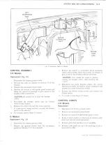
Fig. 4-Blower Motor Assembly
3. Remove the nuts from the distributor duct studs
projecting into the engine compartment.
LIGHT DUTY TRUCK SERVICE MANUAL
Содержание Light Duty Truck 1973
Страница 1: ......
Страница 4: ......
Страница 6: ......
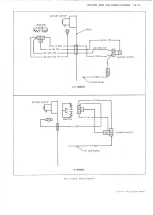
Страница 39: ...HEATER AND AIR CONDITIONING 1A 13 Fig 14 Heater Wiring Diagrams LIGHT DUTY TRUCK SERVICE MANUAL...
Страница 53: ...HEATER AND AIR CONDITIONING 1A 27 LIGHT DUTY TRUCK SERVICE MANUAL...
Страница 115: ...LIGHT DUTY TRUCK SERVICE M A N U A L HEATER AND AIR CONDITIONING 1A 89...
Страница 123: ...BODY 1B 3 Fig 6 Typical 06 Van LIGHT DUTY TRUCK SERVICE MANUAL...
Страница 149: ...BODY 1B 29 Fig 84 Body Mounting 06 Fig 85 Body Mounting 14 LIGHT DUTY TRUCK SERVICE MANUAL...
Страница 171: ...LIGHT DUTY TRUCK SERVICE M A N U A L Fig 2 Frame Horizontal Checking Typical FRAME 2 3...
Страница 173: ...LIGHT DUTY TRUCK SERVICE M A N U A L Fig 4 10 30 Series Truck Frame FRAME 2 5...
Страница 174: ...2 6 FRAME LIGHT DUTY TRUCK SERVICE MANUAL Fig 5 Underbody Reference Points G Van...
Страница 177: ...LIGHT DUTY TRUCK SERVICE MANUAL G 10 20 C 10 P 10 30 Fig 2 Front Suspension C P K Typical FRONT SUSPENSION 3 3...
Страница 185: ...FRONT SUSPENSION 3 11 Fig 16 Toe out on Turns LIGHT DUTY TRUCK SERVICE MANUAL...
Страница 224: ......
Страница 229: ...REAR SUSPENSION AND DRIVELINE 4 5 Fig 13 Rear Spring Installation C K Models LIGHT DUTY TRUCK SERVICE MANUAL...
Страница 266: ......
Страница 310: ...5 44 BRAKES C MODELS G MODELS P MODELS Fig 77 Parking Brake System LIGHT DUTY TRUCK SERVICE MANUAL...
Страница 351: ...ENGINE 6 15 Fig ID Sectional View of Eight Cylinder Engine LIGHT DUTY TRUCK SERVICE MANUAL...
Страница 375: ...EN G IN E 6 39 LIGHT DUTY TRUCK SERVICE MANUAL...
Страница 376: ...6 4 0 ENGINE LIGHT DUTY TRUCK SERVICE MANUAL...
Страница 377: ...ENG IN E 6 41 LIGHT DUTY TRUCK SERVICE MANUAL...
Страница 378: ...LIGHT DUTY TRUCK SERVICE MANUAL Fig 37L K Series Engine Front Mount 6 42 ENG INE...
Страница 379: ...E N G IN E 6 43 FRONT MOUNT REAR MOUNT Fig 38L G Series Engine Mounts LIGHT DUTY TRUCK SERVICE MANUAL...
Страница 400: ...6 6 4 ENG INE LIGHT DUTY TRUCK SERVICE MANUAL...
Страница 401: ...ENG IN E 6 65 LIGHT DUTY TRUCK SERVICE MANUAL...
Страница 402: ...6 6 6 ENGINE LIGHT DUTY TRUCK SERVICE MANUAL...
Страница 403: ...E NG IN E 6 67 Fig 36V C Series Engine Mounts LIGHT DUTY TRUCK SERVICE MANUAL...
Страница 410: ......
Страница 423: ...EN G IN E C OOLING 6K 13 Fig 16 Overheating Chart LIGHT DUTY TRUCK SERVICE MANUAL...
Страница 424: ...6 K 1 4 ENG INE COOLING Fig 17 Coolant Loss Chart LIGHT DUTY TRUCK SERVICE MANUAL...
Страница 455: ...ENGINE FUEL 6M 31 Fig K13 Accelerator Controls P30 42 454 Engine LIGHT DUTY TRUCK SERVICE MANUAL...
Страница 456: ...6M 32 ENGINE FUEL Fig K15 Accelerator Controls G Van L 6 LIGHT DUTY TRUCK SERVICE MANUAL...
Страница 492: ......
Страница 506: ...CEC PLUNGER IS EXTENDED Fig lid Vacuum Advance Diagram Six Cylinder Engine 6T 14 EMISSION CONTROL SYSTEMS...
Страница 512: ...Fig 18e Vacuum Advance Diagram V8 Engine...
Страница 515: ...EMISSION CONTROL SYSTEMS 6T 23 Fig If Six Cylinder A I R System LIGHT DUTY TRUCK SERVICE MANUAL...
Страница 516: ...6 T 2 4 E M IS S IO N CONTROL SYSTEMS LIGHT DUTY TRUCK SERVICE MANUAL...
Страница 517: ...E M IS S IO N C O N TR O L SYSTEM S 6T 25 Fig 4f Diverter Valve Vent Valve LIGHT DUTY TRUCK SERVICE MANUAL...
Страница 528: ......
Страница 540: ...6 Y 1 2 ENGINE ELECTRICAL Fig 16b Battery Installation C K Series LIGHT DUTY TRUCK SERVICE MANUAL...
Страница 572: ...6Y 44 ENGINE ELECTRICAL Fig 25i V 8 Spark Plug Wire Installation LIGHT DUTY TRUCK SERVICE MANUAL...
Страница 590: ......
Страница 592: ...7M 2 CLUTCHES MANUAL TRANSMISSIONS VIEW B Fig la Clutch Linkage Assy C K Models LIGHT DUTY TRUCK SERVICE MANUAL...
Страница 593: ...CLUTCHES MANUAL TRANSMISSIONS 7M 3 LIGHT DUTY TRUCK SERVICE MANUAL...
Страница 594: ...7M 4 CLUTCHES MANUAL TRANSMISSIONS Fig lc Clutch Linkage Assy P Models LIGHT DUTY TRUCK SERVICE MANUAL...
Страница 598: ...7M 8 CLUTCHES MANUAL TRANSMISSIONS LIGHT DUTY TRUCK SERVICE MANUAL...
Страница 642: ......
Страница 654: ......
Страница 656: ...LIGHT DUTY TRUCK SERVICE MANUAL Fig 19M Drive Range Low First Gear Typical 7A 14 AUTOMATIC T R A N S M IS S IO N...
Страница 662: ...LIGHT DUTY TRUCK SERVICE M A N U A L Fig 22M LI Range Manual First Gear Typical 7A 20 AUTOMATIC TRANSMISSION...
Страница 668: ...LIGHT DUTY TRUCK SERVICE M A N U A L Fig 25M Reverse Range Typical 7A 26 AUTOMATIC T R A N S M IS S IO N...
Страница 739: ...FUEL TANKS AND EXHAUST 8 9 Fig 15 Filler Neck and Vent Hose Van LIGHT DUTY TRUCK SERVICE MANUAL...
Страница 740: ...8 10 FUEL TANKS AND EXHAUST Fig 16 Fuel Feed and Return Pipes Front C K LIGHT DUTY TRUCK SERVICE MANUAL...
Страница 743: ...FUEL TANKS AND EXHAUST 8 13 LIGHT DUTY TRUCK SERVICE MANUAL...
Страница 744: ...8 14 FUEL TANKS AND EXHAUST LIGHT DUTY TRUCK SERVICE MANUAL...
Страница 746: ...8 16 FUEL TANKS AND EXHAUST Fig 2 5 Fuel Feed Pipe Front P 105 4 2 LIGHT DUTY TRUCK SERVICE MANUAL...
Страница 760: ...8 30 FUEL TANKS AND EXHAUST Fig 40 Exhaust Pipe P Models LIGHT DUTY TRUCK SERVICE MANUAL...
Страница 761: ...FUEL TANKS AND EXHAUST 8 31 LIGHT DUTY TRUCK SERVICE MANUAL...
Страница 763: ...FUEL TANKS AND EXHAUST 8 33 LIGHT DUTY TRUCK SERVICE MANUAL...
Страница 766: ......
Страница 781: ...STEERING 9 15 OIL PRESSURE OIL RETURN PORT VALVE BODY Fig 21 Left Turn Position LIGHT DUTY TRUCK SERVICE MANUAL...
Страница 832: ...LIGHT DUTY TRUCK SERVICE MANUAL Fig 106 Power Steering Pump Mounting Typical 9 66 STEERING...
Страница 833: ...PUMP ASSEMBLY STEERING GEAR TYPICAL SMALL V8 TYPICAL LARGE V8 STEERING 9 67...
Страница 860: ...9 94 STEERING LEAKAGE AREAS Fig 133 Power Steering Gear Leakage LIGHT DUTY TRUCK SERVICE MANUAL...
Страница 861: ...STEERING 9 95 Fig 134 Power Steering Pump Leakage LIGHT DUTY TRUCK SERVICE MANUAL...
Страница 864: ......
Страница 876: ......
Страница 886: ...11 10 CHASSIS SHEET METAL LIGHT DUTY TRUCK SERVICE MANUAL...
Страница 891: ...ELECTRICAL BODY AND CHASSIS 12 5 LIGHT DUTY TRUCK SERVICE MANUAL...
Страница 897: ...ELECTRICAL BODY AND CHASSIS 12 11 Fig 14 Instrum ent Cluster Assembly C K Models LIGHT DUTY TRUCK SERVICE MANUAL...
Страница 934: ......
Страница 942: ......
Страница 970: ......
Страница 972: ......
Страница 974: ......
Страница 976: ...V...
Страница 978: ......
Страница 979: ......


