HEATER A N D AIR C O N D I T I O N IN G
1A-39
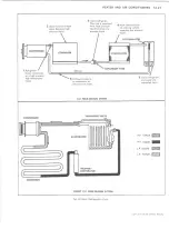
Fig. 43--Floor and Overhead Controls (G Models)
temperature knob and a three speed blower switch. The
controls are mounted on the blower-evaporator cover to
the right of the driver (fig. 43).
The temperature knob is used to control the degree of
cooling desired. Fully clockwise at CITY provides
maximum cooling while turning the knob to HIWAY
provides adequate cooling for highway operation.
The three speed blower fan switch (LOW-MED-HI) is
used to control the quantity of air flow.
NOTE: Reduced cooling and freezing of the
evaporator could be encountered when
operating at highway speeds with the controls
at the "CITY" setting.
Overhead System (G Models)
This system operates in conjunction with the front floor
mounted system. Since refrigerant is controlled by the
front system the only control provided on the rear
overhead system in a three speed blower switch (fig. 43).
In the OFF position, the blower is inoperative; however,
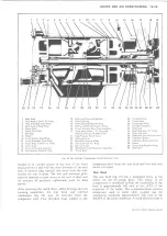
Fig. 44- Motor Home Unit Control
refrigerant is circulating in the system if the front system
in ON. To operate the rear overhead system, simply
select the desired blower speed (LOW, MED, HI).
NOTE: The rear unit will not operate unless
the front unit is calling for cooling.
Dash Mounted Unit (Motor Home Chassis
Units)
This system is self contained and is mounted below the
dash by the body manufacturer. System controls consist
of an AIR knob and TEMP knob located in the center of
the unit face plate (fig. 44).
Air Knob
Turning the AIR knob clockwise operates a three speed
(LOW-MED-HI) blower motor.
Temp Knob
This knob is used to control the degree of cooling
desired. Fully clockwise at CITY provides maximum
cooling, while turning the knob to HIWAY provides
adequate cooling for highway operation.
NOTE: Reduced cooling could be encoun
tered when operating at highway speeds with
the controls at the CITY setting. The heater
must be fully off to obtain maximum cooling.
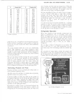
GENERAL IN FO R M A T IO N
In any vocation or trade, there are established
procedures and practices that have been developed after
many years of experience. In addition, occupational
hazards may be present that require the observation of
certain precautions or use of special tools and
equipment. Observing the procedures, practices and
precautions of servicing refrigeration equipment will
greatly reduce the possibilities of damage to the
customers’ equipment as well as virtually eliminate the
element of hazard to the serviceman.
PRECAUTIONS IN HANDLING
REFRIGERANT-12
Refrigerant-12 is transparent and colorless in both the
gaseous and liquid state. It has a boiling point of 21.7°F
below zero and, therefore, at all normal temperatures
and pressures it will be a vapor. The vapor is heavier
than air, and is noninflammable, nonexplosive, nonpoi-
sonous (except when in contact with an open flame) and
noncorrosive (except when in contact with water).
WARNING:
The following precautions in
handling R-12 should be observed at all
times.
• If it is ever necessary to transport or carry a cylinder
or can of refrigerant in a car, keep it in the luggage
compartment. Refrigerant should not be exposed to
the radiant heat from the sun since the resulting
increase in pressure may cause the safety valve to
release or the cylinder or can to burst.
LIGHT DUTY TRUCK SERVICE MANUAL
Содержание Light Duty Truck 1973
Страница 1: ......
Страница 4: ......
Страница 6: ......
Страница 39: ...HEATER AND AIR CONDITIONING 1A 13 Fig 14 Heater Wiring Diagrams LIGHT DUTY TRUCK SERVICE MANUAL...
Страница 53: ...HEATER AND AIR CONDITIONING 1A 27 LIGHT DUTY TRUCK SERVICE MANUAL...
Страница 115: ...LIGHT DUTY TRUCK SERVICE M A N U A L HEATER AND AIR CONDITIONING 1A 89...
Страница 123: ...BODY 1B 3 Fig 6 Typical 06 Van LIGHT DUTY TRUCK SERVICE MANUAL...
Страница 149: ...BODY 1B 29 Fig 84 Body Mounting 06 Fig 85 Body Mounting 14 LIGHT DUTY TRUCK SERVICE MANUAL...
Страница 171: ...LIGHT DUTY TRUCK SERVICE M A N U A L Fig 2 Frame Horizontal Checking Typical FRAME 2 3...
Страница 173: ...LIGHT DUTY TRUCK SERVICE M A N U A L Fig 4 10 30 Series Truck Frame FRAME 2 5...
Страница 174: ...2 6 FRAME LIGHT DUTY TRUCK SERVICE MANUAL Fig 5 Underbody Reference Points G Van...
Страница 177: ...LIGHT DUTY TRUCK SERVICE MANUAL G 10 20 C 10 P 10 30 Fig 2 Front Suspension C P K Typical FRONT SUSPENSION 3 3...
Страница 185: ...FRONT SUSPENSION 3 11 Fig 16 Toe out on Turns LIGHT DUTY TRUCK SERVICE MANUAL...
Страница 224: ......
Страница 229: ...REAR SUSPENSION AND DRIVELINE 4 5 Fig 13 Rear Spring Installation C K Models LIGHT DUTY TRUCK SERVICE MANUAL...
Страница 266: ......
Страница 310: ...5 44 BRAKES C MODELS G MODELS P MODELS Fig 77 Parking Brake System LIGHT DUTY TRUCK SERVICE MANUAL...
Страница 351: ...ENGINE 6 15 Fig ID Sectional View of Eight Cylinder Engine LIGHT DUTY TRUCK SERVICE MANUAL...
Страница 375: ...EN G IN E 6 39 LIGHT DUTY TRUCK SERVICE MANUAL...
Страница 376: ...6 4 0 ENGINE LIGHT DUTY TRUCK SERVICE MANUAL...
Страница 377: ...ENG IN E 6 41 LIGHT DUTY TRUCK SERVICE MANUAL...
Страница 378: ...LIGHT DUTY TRUCK SERVICE MANUAL Fig 37L K Series Engine Front Mount 6 42 ENG INE...
Страница 379: ...E N G IN E 6 43 FRONT MOUNT REAR MOUNT Fig 38L G Series Engine Mounts LIGHT DUTY TRUCK SERVICE MANUAL...
Страница 400: ...6 6 4 ENG INE LIGHT DUTY TRUCK SERVICE MANUAL...
Страница 401: ...ENG IN E 6 65 LIGHT DUTY TRUCK SERVICE MANUAL...
Страница 402: ...6 6 6 ENGINE LIGHT DUTY TRUCK SERVICE MANUAL...
Страница 403: ...E NG IN E 6 67 Fig 36V C Series Engine Mounts LIGHT DUTY TRUCK SERVICE MANUAL...
Страница 410: ......
Страница 423: ...EN G IN E C OOLING 6K 13 Fig 16 Overheating Chart LIGHT DUTY TRUCK SERVICE MANUAL...
Страница 424: ...6 K 1 4 ENG INE COOLING Fig 17 Coolant Loss Chart LIGHT DUTY TRUCK SERVICE MANUAL...
Страница 455: ...ENGINE FUEL 6M 31 Fig K13 Accelerator Controls P30 42 454 Engine LIGHT DUTY TRUCK SERVICE MANUAL...
Страница 456: ...6M 32 ENGINE FUEL Fig K15 Accelerator Controls G Van L 6 LIGHT DUTY TRUCK SERVICE MANUAL...
Страница 492: ......
Страница 506: ...CEC PLUNGER IS EXTENDED Fig lid Vacuum Advance Diagram Six Cylinder Engine 6T 14 EMISSION CONTROL SYSTEMS...
Страница 512: ...Fig 18e Vacuum Advance Diagram V8 Engine...
Страница 515: ...EMISSION CONTROL SYSTEMS 6T 23 Fig If Six Cylinder A I R System LIGHT DUTY TRUCK SERVICE MANUAL...
Страница 516: ...6 T 2 4 E M IS S IO N CONTROL SYSTEMS LIGHT DUTY TRUCK SERVICE MANUAL...
Страница 517: ...E M IS S IO N C O N TR O L SYSTEM S 6T 25 Fig 4f Diverter Valve Vent Valve LIGHT DUTY TRUCK SERVICE MANUAL...
Страница 528: ......
Страница 540: ...6 Y 1 2 ENGINE ELECTRICAL Fig 16b Battery Installation C K Series LIGHT DUTY TRUCK SERVICE MANUAL...
Страница 572: ...6Y 44 ENGINE ELECTRICAL Fig 25i V 8 Spark Plug Wire Installation LIGHT DUTY TRUCK SERVICE MANUAL...
Страница 590: ......
Страница 592: ...7M 2 CLUTCHES MANUAL TRANSMISSIONS VIEW B Fig la Clutch Linkage Assy C K Models LIGHT DUTY TRUCK SERVICE MANUAL...
Страница 593: ...CLUTCHES MANUAL TRANSMISSIONS 7M 3 LIGHT DUTY TRUCK SERVICE MANUAL...
Страница 594: ...7M 4 CLUTCHES MANUAL TRANSMISSIONS Fig lc Clutch Linkage Assy P Models LIGHT DUTY TRUCK SERVICE MANUAL...
Страница 598: ...7M 8 CLUTCHES MANUAL TRANSMISSIONS LIGHT DUTY TRUCK SERVICE MANUAL...
Страница 642: ......
Страница 654: ......
Страница 656: ...LIGHT DUTY TRUCK SERVICE MANUAL Fig 19M Drive Range Low First Gear Typical 7A 14 AUTOMATIC T R A N S M IS S IO N...
Страница 662: ...LIGHT DUTY TRUCK SERVICE M A N U A L Fig 22M LI Range Manual First Gear Typical 7A 20 AUTOMATIC TRANSMISSION...
Страница 668: ...LIGHT DUTY TRUCK SERVICE M A N U A L Fig 25M Reverse Range Typical 7A 26 AUTOMATIC T R A N S M IS S IO N...
Страница 739: ...FUEL TANKS AND EXHAUST 8 9 Fig 15 Filler Neck and Vent Hose Van LIGHT DUTY TRUCK SERVICE MANUAL...
Страница 740: ...8 10 FUEL TANKS AND EXHAUST Fig 16 Fuel Feed and Return Pipes Front C K LIGHT DUTY TRUCK SERVICE MANUAL...
Страница 743: ...FUEL TANKS AND EXHAUST 8 13 LIGHT DUTY TRUCK SERVICE MANUAL...
Страница 744: ...8 14 FUEL TANKS AND EXHAUST LIGHT DUTY TRUCK SERVICE MANUAL...
Страница 746: ...8 16 FUEL TANKS AND EXHAUST Fig 2 5 Fuel Feed Pipe Front P 105 4 2 LIGHT DUTY TRUCK SERVICE MANUAL...
Страница 760: ...8 30 FUEL TANKS AND EXHAUST Fig 40 Exhaust Pipe P Models LIGHT DUTY TRUCK SERVICE MANUAL...
Страница 761: ...FUEL TANKS AND EXHAUST 8 31 LIGHT DUTY TRUCK SERVICE MANUAL...
Страница 763: ...FUEL TANKS AND EXHAUST 8 33 LIGHT DUTY TRUCK SERVICE MANUAL...
Страница 766: ......
Страница 781: ...STEERING 9 15 OIL PRESSURE OIL RETURN PORT VALVE BODY Fig 21 Left Turn Position LIGHT DUTY TRUCK SERVICE MANUAL...
Страница 832: ...LIGHT DUTY TRUCK SERVICE MANUAL Fig 106 Power Steering Pump Mounting Typical 9 66 STEERING...
Страница 833: ...PUMP ASSEMBLY STEERING GEAR TYPICAL SMALL V8 TYPICAL LARGE V8 STEERING 9 67...
Страница 860: ...9 94 STEERING LEAKAGE AREAS Fig 133 Power Steering Gear Leakage LIGHT DUTY TRUCK SERVICE MANUAL...
Страница 861: ...STEERING 9 95 Fig 134 Power Steering Pump Leakage LIGHT DUTY TRUCK SERVICE MANUAL...
Страница 864: ......
Страница 876: ......
Страница 886: ...11 10 CHASSIS SHEET METAL LIGHT DUTY TRUCK SERVICE MANUAL...
Страница 891: ...ELECTRICAL BODY AND CHASSIS 12 5 LIGHT DUTY TRUCK SERVICE MANUAL...
Страница 897: ...ELECTRICAL BODY AND CHASSIS 12 11 Fig 14 Instrum ent Cluster Assembly C K Models LIGHT DUTY TRUCK SERVICE MANUAL...
Страница 934: ......
Страница 942: ......
Страница 970: ......
Страница 972: ......
Страница 974: ......
Страница 976: ...V...
Страница 978: ......
Страница 979: ......


