HEATER A N D AIR C O N D I T IO N I N G
1A-3
THEORY OF OPERATION
BLOWER AND AIR INLET ASSEMBLY
The blower and air inlet assembly draws outside air
through the outside air inlet grille located forward of the
windshield reveal molding and channels the air into the
heater distributor assembly. The operation of the blower
motor is controlled by the FAN switch on the heater
control. The motor is connected in series with the FAN
switch and also the blower resistor assembly. Located in
the fuse block, in series between the blower motor and
the battery, is a 25 amp. fuse C-K models - a 20 amp
fuse on G models.
HEATER DISTRIBUTOR ASSEMBLY
The heater distributor assembly houses the heater core
and the doors necessary to control mixing and
channeling of the air. Since the unit has no water valve,
water circulation keeps the core hot at all times. That
portion of the air passing through the core receives
maximum heat from the core. Air entering the
distributor assembly is channeled as follows:
C-K Models
Air entering the distributor can be directed out the purge
door opening, on the right end of the distributor
assembly, by the purge door. If the purge door is closed,
then air is directed through and/or around the heater
core by the temperature door. Air is then directed into
the passenger compartment through the heater (floor)
outlets and/or the defroster (dash) outlets by the
defroster door. The temperature of the outlet air is
dependent on the ratio of heated to unheated air
(controlled by the temperature door).
G Models
Airflow is controlled by three doors in the distributor
assembly. The air door can be adjusted to vary airflow. If
air is allowed to enter the distributor assembly, it is then
directed through and/or around the heater core by the
temperature door. Air is directed into the passenger
compartment through the heater (floor) and/or defroster
(dash) outlets by the defroster door. The temperature of
the outlet air is dependent on the ratio of heated to
unheated air (controlled by the temperature door).
TURE door in the heater distributor assembly. All
incoming "outside" air is directed around the heater core
in the COLD position or through the core in the HOT
position. The desired outlet temperature is obtained by
blending the heated and unheated air according to the
setting of the temperature lever.
Heater-Def Lever
The HEATER-DEF lever controls the position of the
DEFROSTER door and the PURGE door. In the OFF
position, the blower is "on" and incoming air is directed
up under the dash through the purge door opening. As
the lever is moved to the right of the OFF position, the
door closes, directing airflow on into the distributor
assembly. With the lever at HEATER, the DEFROSTER
door directs almost all airflow to the heater (floor) outlets
- a small amount of air is directed to the defroster (dash)
outlets. In the DEF position, most airflow is diverted to
the defroster outlets. Moving the lever part way, as
desired, will split airflow between the floor and defroster
outlets.
Fan Control
The blower fan lever is located at the left hand side of
the control assembly. The blower motor will operate as
soon as the ignition switch is turned to the RUN
position. The control has three positions only; LO, MED,
HI. There is no OFF position.
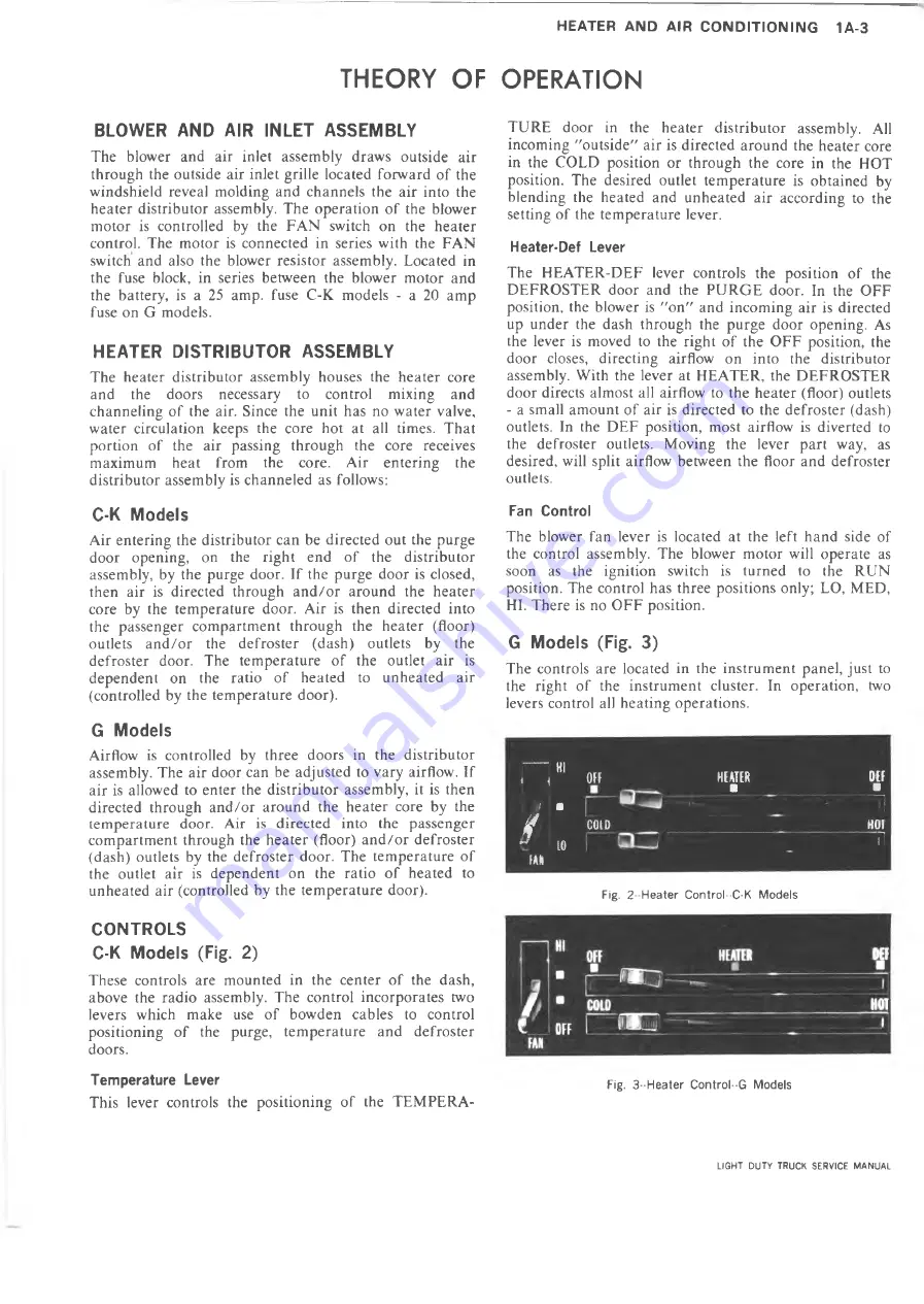
G Models (Fig. 3)
The controls are located in the instrument panel, just to
the right of the instrument cluster. In operation, two
levers control all heating operations.
—
Hl
<
\
OFF
HEATER
■
DEF
■
I - ■
-
.
_ j
j f
C01D
H OI
~
10
FAN
, j
-
n
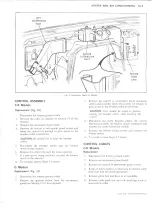
Fig. 2-Heater Control--C-K Models
CONTROLS
C-K Models (Fig. 2)
These controls are mounted in the center of the dash,
above the radio assembly. The control incorporates two
levers which make use of bowden cables to control
positioning of the purge, temperature and defroster
doors.
Temperature Lever
This lever controls the positioning of the TEMPERA-
Fig. 3-Heater Control-G Models
LIGHT DUTY TRUCK SERVICE MANUAL
Содержание Light Duty Truck 1973
Страница 1: ......
Страница 4: ......
Страница 6: ......
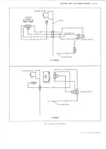
Страница 39: ...HEATER AND AIR CONDITIONING 1A 13 Fig 14 Heater Wiring Diagrams LIGHT DUTY TRUCK SERVICE MANUAL...
Страница 53: ...HEATER AND AIR CONDITIONING 1A 27 LIGHT DUTY TRUCK SERVICE MANUAL...
Страница 115: ...LIGHT DUTY TRUCK SERVICE M A N U A L HEATER AND AIR CONDITIONING 1A 89...
Страница 123: ...BODY 1B 3 Fig 6 Typical 06 Van LIGHT DUTY TRUCK SERVICE MANUAL...
Страница 149: ...BODY 1B 29 Fig 84 Body Mounting 06 Fig 85 Body Mounting 14 LIGHT DUTY TRUCK SERVICE MANUAL...
Страница 171: ...LIGHT DUTY TRUCK SERVICE M A N U A L Fig 2 Frame Horizontal Checking Typical FRAME 2 3...
Страница 173: ...LIGHT DUTY TRUCK SERVICE M A N U A L Fig 4 10 30 Series Truck Frame FRAME 2 5...
Страница 174: ...2 6 FRAME LIGHT DUTY TRUCK SERVICE MANUAL Fig 5 Underbody Reference Points G Van...
Страница 177: ...LIGHT DUTY TRUCK SERVICE MANUAL G 10 20 C 10 P 10 30 Fig 2 Front Suspension C P K Typical FRONT SUSPENSION 3 3...
Страница 185: ...FRONT SUSPENSION 3 11 Fig 16 Toe out on Turns LIGHT DUTY TRUCK SERVICE MANUAL...
Страница 224: ......
Страница 229: ...REAR SUSPENSION AND DRIVELINE 4 5 Fig 13 Rear Spring Installation C K Models LIGHT DUTY TRUCK SERVICE MANUAL...
Страница 266: ......
Страница 310: ...5 44 BRAKES C MODELS G MODELS P MODELS Fig 77 Parking Brake System LIGHT DUTY TRUCK SERVICE MANUAL...
Страница 351: ...ENGINE 6 15 Fig ID Sectional View of Eight Cylinder Engine LIGHT DUTY TRUCK SERVICE MANUAL...
Страница 375: ...EN G IN E 6 39 LIGHT DUTY TRUCK SERVICE MANUAL...
Страница 376: ...6 4 0 ENGINE LIGHT DUTY TRUCK SERVICE MANUAL...
Страница 377: ...ENG IN E 6 41 LIGHT DUTY TRUCK SERVICE MANUAL...
Страница 378: ...LIGHT DUTY TRUCK SERVICE MANUAL Fig 37L K Series Engine Front Mount 6 42 ENG INE...
Страница 379: ...E N G IN E 6 43 FRONT MOUNT REAR MOUNT Fig 38L G Series Engine Mounts LIGHT DUTY TRUCK SERVICE MANUAL...
Страница 400: ...6 6 4 ENG INE LIGHT DUTY TRUCK SERVICE MANUAL...
Страница 401: ...ENG IN E 6 65 LIGHT DUTY TRUCK SERVICE MANUAL...
Страница 402: ...6 6 6 ENGINE LIGHT DUTY TRUCK SERVICE MANUAL...
Страница 403: ...E NG IN E 6 67 Fig 36V C Series Engine Mounts LIGHT DUTY TRUCK SERVICE MANUAL...
Страница 410: ......
Страница 423: ...EN G IN E C OOLING 6K 13 Fig 16 Overheating Chart LIGHT DUTY TRUCK SERVICE MANUAL...
Страница 424: ...6 K 1 4 ENG INE COOLING Fig 17 Coolant Loss Chart LIGHT DUTY TRUCK SERVICE MANUAL...
Страница 455: ...ENGINE FUEL 6M 31 Fig K13 Accelerator Controls P30 42 454 Engine LIGHT DUTY TRUCK SERVICE MANUAL...
Страница 456: ...6M 32 ENGINE FUEL Fig K15 Accelerator Controls G Van L 6 LIGHT DUTY TRUCK SERVICE MANUAL...
Страница 492: ......
Страница 506: ...CEC PLUNGER IS EXTENDED Fig lid Vacuum Advance Diagram Six Cylinder Engine 6T 14 EMISSION CONTROL SYSTEMS...
Страница 512: ...Fig 18e Vacuum Advance Diagram V8 Engine...
Страница 515: ...EMISSION CONTROL SYSTEMS 6T 23 Fig If Six Cylinder A I R System LIGHT DUTY TRUCK SERVICE MANUAL...
Страница 516: ...6 T 2 4 E M IS S IO N CONTROL SYSTEMS LIGHT DUTY TRUCK SERVICE MANUAL...
Страница 517: ...E M IS S IO N C O N TR O L SYSTEM S 6T 25 Fig 4f Diverter Valve Vent Valve LIGHT DUTY TRUCK SERVICE MANUAL...
Страница 528: ......
Страница 540: ...6 Y 1 2 ENGINE ELECTRICAL Fig 16b Battery Installation C K Series LIGHT DUTY TRUCK SERVICE MANUAL...
Страница 572: ...6Y 44 ENGINE ELECTRICAL Fig 25i V 8 Spark Plug Wire Installation LIGHT DUTY TRUCK SERVICE MANUAL...
Страница 590: ......
Страница 592: ...7M 2 CLUTCHES MANUAL TRANSMISSIONS VIEW B Fig la Clutch Linkage Assy C K Models LIGHT DUTY TRUCK SERVICE MANUAL...
Страница 593: ...CLUTCHES MANUAL TRANSMISSIONS 7M 3 LIGHT DUTY TRUCK SERVICE MANUAL...
Страница 594: ...7M 4 CLUTCHES MANUAL TRANSMISSIONS Fig lc Clutch Linkage Assy P Models LIGHT DUTY TRUCK SERVICE MANUAL...
Страница 598: ...7M 8 CLUTCHES MANUAL TRANSMISSIONS LIGHT DUTY TRUCK SERVICE MANUAL...
Страница 642: ......
Страница 654: ......
Страница 656: ...LIGHT DUTY TRUCK SERVICE MANUAL Fig 19M Drive Range Low First Gear Typical 7A 14 AUTOMATIC T R A N S M IS S IO N...
Страница 662: ...LIGHT DUTY TRUCK SERVICE M A N U A L Fig 22M LI Range Manual First Gear Typical 7A 20 AUTOMATIC TRANSMISSION...
Страница 668: ...LIGHT DUTY TRUCK SERVICE M A N U A L Fig 25M Reverse Range Typical 7A 26 AUTOMATIC T R A N S M IS S IO N...
Страница 739: ...FUEL TANKS AND EXHAUST 8 9 Fig 15 Filler Neck and Vent Hose Van LIGHT DUTY TRUCK SERVICE MANUAL...
Страница 740: ...8 10 FUEL TANKS AND EXHAUST Fig 16 Fuel Feed and Return Pipes Front C K LIGHT DUTY TRUCK SERVICE MANUAL...
Страница 743: ...FUEL TANKS AND EXHAUST 8 13 LIGHT DUTY TRUCK SERVICE MANUAL...
Страница 744: ...8 14 FUEL TANKS AND EXHAUST LIGHT DUTY TRUCK SERVICE MANUAL...
Страница 746: ...8 16 FUEL TANKS AND EXHAUST Fig 2 5 Fuel Feed Pipe Front P 105 4 2 LIGHT DUTY TRUCK SERVICE MANUAL...
Страница 760: ...8 30 FUEL TANKS AND EXHAUST Fig 40 Exhaust Pipe P Models LIGHT DUTY TRUCK SERVICE MANUAL...
Страница 761: ...FUEL TANKS AND EXHAUST 8 31 LIGHT DUTY TRUCK SERVICE MANUAL...
Страница 763: ...FUEL TANKS AND EXHAUST 8 33 LIGHT DUTY TRUCK SERVICE MANUAL...
Страница 766: ......
Страница 781: ...STEERING 9 15 OIL PRESSURE OIL RETURN PORT VALVE BODY Fig 21 Left Turn Position LIGHT DUTY TRUCK SERVICE MANUAL...
Страница 832: ...LIGHT DUTY TRUCK SERVICE MANUAL Fig 106 Power Steering Pump Mounting Typical 9 66 STEERING...
Страница 833: ...PUMP ASSEMBLY STEERING GEAR TYPICAL SMALL V8 TYPICAL LARGE V8 STEERING 9 67...
Страница 860: ...9 94 STEERING LEAKAGE AREAS Fig 133 Power Steering Gear Leakage LIGHT DUTY TRUCK SERVICE MANUAL...
Страница 861: ...STEERING 9 95 Fig 134 Power Steering Pump Leakage LIGHT DUTY TRUCK SERVICE MANUAL...
Страница 864: ......
Страница 876: ......
Страница 886: ...11 10 CHASSIS SHEET METAL LIGHT DUTY TRUCK SERVICE MANUAL...
Страница 891: ...ELECTRICAL BODY AND CHASSIS 12 5 LIGHT DUTY TRUCK SERVICE MANUAL...
Страница 897: ...ELECTRICAL BODY AND CHASSIS 12 11 Fig 14 Instrum ent Cluster Assembly C K Models LIGHT DUTY TRUCK SERVICE MANUAL...
Страница 934: ......
Страница 942: ......
Страница 970: ......
Страница 972: ......
Страница 974: ......
Страница 976: ...V...
Страница 978: ......
Страница 979: ......


