


HEATER AND AIR CONDITIONING 1A-7
AIR CONDITIONING
INDEX
Page
Four-Season System ........................................................................... ..1A-7
Roof-Mounted System .........................................................................1A-9
GM Chevrolet S y s te m ......... ...................................... .. . . , .............. ..1A-10
Precautions in Handling Refrigerant-12........................................... ..1A-12
Precautions in Handling Refrigerant Line s.........................................1A-12
Maintaining Chemical Stability in the
J-8393 Charging Station .................................................................... ..1A-13
Gauge Set ................................................................................................1A-14
Vacuum P u m p ........................... ........... ........................... .................... ..1A-14
Leak Testing the S y ste m .......................................................................1A-15
Availability o f Refrigerant-1 2 ..............................................................1A-15
Compressor O i l .......................................................................................1A-16
Compressor Serial Number ................................................................ ..1A-16
Inspection and Periodic Service ..............................................................1A-16
Pre-Delivery In sp e ctio n ....................................................................... ..1A-16
6000 Mile Inspection........................................................................... ..1A-16
Periodic Service.......................................................................................1A-16
Installing Charging Station to Check System
Performance Test ..................................................................................1A-16
Performance D a t a ................................................................................ ..1A-17
Evaporator Control Valve (P O A ).........................................................1A-18
Thermostatic S w itc h ........................................................................... ..1A-18
Expansion V a lv e .................................................................................. ..1A-19
Engine Idle C om pensator....................................................................1A-20
Evacuating and Charging Procedures .................................................. ..1A-20
Refrigerant Quick-Check Procedure . . ..............................................1A-22
Component Replacement and Minor R e p a irs .......................................1A-23
Preparing System for Replacement o f
Component Parts........................................................................... ..1A-23
Foreign Material in the System ....................................................... ..1A-23
Refrigerant Line Connections......................................................... ..1A-23
Repair o f Refrigerant L e a k s ........................................................... ..1A-24
Refrigerant Hose Failure ................................................................ ..1A-24
Compressor .........................................................................................1A-25
Condenser ......................................................................................... ..1A-26
Page
Receiver-Dehydrator ....................................................................... ..1A-26
Sight Glass Replacement ................................................................ ..1A-26
Blower A ss e m b ly .............................................................................. ..1A-27
Evaporator C o r e ................................................................................ ..1A-27
Blower and Evaporator Case..............................................................1A-28
Expansion V alve ................................................................................ ..1A-29
Muffler, Connector Block and Hose A sse m b ly ........................... ..1A-29
POA V a lv e ......................................................................................... ..1A-30
Anti-Dieseling R e la y ......................................................................... ..1A-32
Compressor Clutch S w itc h .............................................................. ..1A-32
Blower Resistor Unit ....................................................................... ..1A-32
Kick Panel Air Valve ....................................................................... ..1A-33
Plenum Air V a lv e .............................................................................. ..1A-33
Roof-Mounted System ....................................................................... ..1A-34
Compressor, Condenser, Receiver-Dehydrator
Control Switch and/or Front D u c t ................................................ ..1A-34
Intermediate Duct ..............................................................................1A-35
Thermostatic Switch, Blower M otor Relay
and/or Blower M otor Resistor.......................................................1A-35
Blower Motor Assemblies................................................................ .. 1A-35
Expansion V alve ................................................................................ ..1A-36
Evaporator C o r e ................................................................................ ..1A-37
Muffler and Connector B lo c k ......................................................... ..1A-37
Anti-Dieseling R e la y ......................................................................... ..1A-37
Compressor, Condenser, Receiver-Dehydrator
Blower and/or Thermostatic Switches ......................................... ..1A-38
Evaporator Core, Expansion Valve, Blower Motor
GENERAL DESCRIPTION
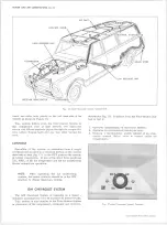
FOUR-SEASON SYSTEM
The Four-Season system uses an evaporator pressure
control known as the POA (Pressure Operated Absolute)
valve.
The six-cylinder reciprocating compressor is
bracket-mounted to the engine and belt driven from the
crankshaft pulley. The condenser is mounted ahead of the
engine cooling radiator and the receiver-dehydrator is
mounted in the refrigerant line downstream of the con
denser.
All cooling system components are connected
by means of flexible refrigerant lines.
Both the heating and cooling functions are performed
by this system.
Air entering the vehicle must pass
either through the cooling unit (evaporator) or through
the heating unit, or through both. The system is thus
referred to as a parallel system.
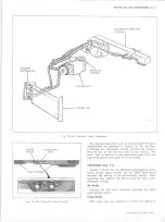
Fig. 13— Four Season System Controls
10-30 CHEVROLET TRUCK SERVICE MANUAL
Содержание 10 1971 Series
Страница 1: ......
Страница 96: ......
Страница 100: ...10 30 CHEVROLET TRUCK SERVICE MANUAL Fig 4 10 30 Series Truck Frame FRAME 2 4 ...
Страница 120: ......
Страница 203: ...ENGINE 6 25 Fig 22L Engine Mounts 10 30 CHEVROLET TRUCK SERVICE MANUAL ...
Страница 215: ...ENGINE 6 37 REAR M O U NT Fig 21V Engine Mounts 10 30 CHEVROLET TRUCK SERVICE MANUAL ...
Страница 218: ......
Страница 249: ......
Страница 250: ...EMISSION CONTROL SYSTEMS 6T 4 Fig 3 Combination Emission Control System Routing V8 10 30 CHEVROLET TRUCK SERVICE MANUAL ...
Страница 324: ......
Страница 339: ...FUEL TANK AND EXHAUST SYSTEMS 8 15 SPECIAL TOOLS Fig 22 Special Tools 1 J 23346 Fuel Tank Gauge Remover and Installer ...
Страница 340: ......
Страница 365: ...10 30 CHEVROLET TRUCK SERVICE MANUAL Fig 43 Power Steering Pump M ounting STEERING 9 25 ...
Страница 368: ......
Страница 386: ......
Страница 390: ...ELECTRICAL BODY AND CHASSIS 12 4 10 30 CHEVROLET TRUCK SERVICE MANUAL ...
Страница 391: ......
Страница 392: ...ELECTRICAL BODY AND CHASSIS 12 6 Fig 5 Rear Lighting Composite 10 30 CHEVROLET TRUCK SERVICE MANUAL ...
Страница 409: ...ELECTRICAL BODY AND CHASSIS 12 23 Fig 27 Engine Compartment CA30 02 10 30 CHEVROLET TRUCK SERVICE MANUAL ...
Страница 410: ...ELECTRICAL BODY AND CHASSIS 12 24 18DK GRN 19 Fig 28 Instrument Panel CA30 02 10 30 CHEVROLET TRUCK SERVICE MANUAL ...
Страница 411: ...ELECTRICAL BODY AND CHASSIS 12 25 Fig 29 Instrument Panel CA30 02 10 30 CHEVROLET TRUCK SERVICE MANUAL ...
Страница 412: ...ELECTRICAL BODY AND CHASSIS 12 26 fh Ar r kk 4 Fig 30 Engine Compartment C A K A 10 20 CA30 03 z _ ...
Страница 416: ...ELECTRICAL BODY AND CHASSIS 12 30 Fig 34 Engine Compartment CA KA10 20 CA30 04 10 30 CHEVROLET TRUCK SERVICE MANUAL ...
Страница 420: ...ELECTRICAL BODY AND CHASSIS 12 34 Fig 38 Engine Compartment C A K A 1 0 20 06 16 10 30 CHEVROLET TRUCK SERVICE MANUAL ...
Страница 422: ...ELECTRICAL BODY AND CHASSIS 12 36 Fig 40 Instrument Panel C A K A 10 20 06 16 10 30 CHEVROLET TRUCK SERVICE MANUAL ...
Страница 423: ...ELECTRICAL BODY AND CHASSIS 12 37 Fig 41 R ear Lamps C A K A 1 0 20 06 16 10 30 CHEVROLET TRUCK SERVICE MANUAL ...
Страница 424: ...ELECTRICAL BODY AND CHASSIS 12 38 Fig 42 Engine Compartment CA KA10 20 CAl30 14 34 10 30 CHEVROLET TRUCK SERVICE MANUAL ...
Страница 426: ...ELECTRICAL BODY AND CHASSIS 12 40 Fig 44 Instrument Panel CA KA10 20 CA30 14 34 10 30 CHEVROLET TRUCK SERVICE MANUAL ...
Страница 428: ......
Страница 432: ......
Страница 449: ...SPECIFICATIONS 9 10 30 CHEVROLET TRUCK SERVICE MANUAL ...
Страница 463: ......
Страница 464: ......
Страница 465: ......
Страница 466: ......