


HEATER AND AIR CONDITIONING 1A-16
COMPRESSOR OIL
Special refrigeration lubricant should be used in the
system.
This oil is as free from moisture and con
taminants as it is possible to attain by human processes.
This condition should be preserved by immediately cap
ping the bottle when not in use.
See "Air Conditioning System Capacities" for the total
system oil capacity.
Due to the porosity of the refrigerant hoses and con
nections, the system refrigerant level will show a definite
drop after a period of time. Since the compressor oil is
carried throughout the entire system mixed with the
refrigerant, a low refrigerant level will cause a danger
ous lack of lubrication. Therefore the refrigerant charge
in the system has a definite tie-in with the amount of oil
found in the compressor and an insufficient charge may
eventually lead to an oil build-up in the evaporator.
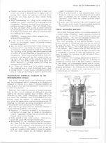
COMPRESSOR SERIAL NUMBER
The compressor serial number is located on the serial
number plate on top of the compressor. The serial num
ber consists of a series of numbers and letters. This
serial number should be referenced on all forms and
correspondence related to the servicing of this part.
INSPECTION A N D PERIODIC SERVICE
PRE-DELIVERY INSPECTION
1. Check that engine exhaust is suitably ventilated.
2. Check the belt for proper tension.
3. With controls positioned for operation of the system,
operate the unit for ten minutes at approximately
2000 rpm. Observe the clutch pulley bolt to see that
the compressor is operating at the same speed as
the clutch pulley.
Any speed variation indicates
clutch slippage.
4. Before turning off the engine, check the sight glass
to see that the unit has a sufficient Refrigerant
charge. The glass should be clear, although during
milder weather it may show traces of bubbles. Foam
in the flow indicates a low charge. No liquid visible
and no temperature differential between compressor
inlet and outlet lines, indicates no charge.
5. Check refrigerant hose connections:
"O" ring Connections - Check torque of fittings as
charted later in this section under "Refrigerant Line
Connections;" retorque if required. Leak test the
complete system.
Hose Clamp Connections - If clamp screw torque is
less than 10 in. lb., retighten to 20-25 in. lbs. Do
not tighten to new hose specifications or hose leakage
may occur. Leak test the complete system.
6. If there is evidence of an oil leak, check the com
pressor to see that the oil charge is satisfactory.
NOTE:
A slight amount of oil leakage at the
compressor front seal is considered normal.
7. Check the system controls for proper operation.
6000 MILE INSPECTION
1. Check unit for any indication of a refrigerant leak.
2. If there is an indication of an oil leak, check the
compressor for proper oil charge.
NOTE:
A slight amount of oil leakage at the
compressor front seal is considered normal.
3. Check sight glass for proper charge of Refriger
ant-12.
4. Tighten the compressor brace and support bolts and
check the belt tension.
5. Check refrigerant hose connections as in Step 5 of
"Pre-Delivery Inspection."
PERIODIC SERVICE
• Inspect condenser regularly to be sure that the fins
are not plugged with leaves or other foreign material.
• Check evaporator drain tubes regularly for dirt or
restrictions.
• At least once a year, check the system for proper
refrigerant charge and the flexible hoses for brittle
ness, wear or leaks.
• Every
6000
miles check sight glass for low refrig
erant level.
• Check belt tension regularly.
INSTALLING CH AR G IN G STATION TO CHECK
SYSTEM OPERATION
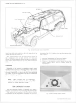
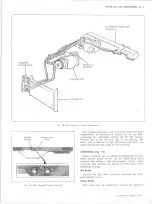
1. Four Season System - The low pressure fitting is
located on the POA valve. The high pressure fitting
is located on the muffler (fig.
25).
NOTE:
The connector assembly consists of in
let (suction) and outlet (discharge) lines with the
freon hoses swaged to the metal lines (fig.
25).
Roof-Mounted and GM Chevrolet Systems - The low
pressure fitting is located on the connector block and
the high pressure fitting on the muffler (fig.
25).
2.
Install Gauge Adapters
J -5 4 2 0
and
J -9 4 5 9
onto the
high and low pressure gauge lines.
3. With the engine stopped, remove the caps from the
cored valve gauge fittings.
4.
Be certain all valves on charging station are closed.
5.
Connect high pressure gauge line to high pressure
gauge fitting.
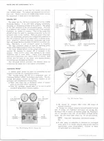
6.
See Figure
22.
Turn high pressure control
(2)
one
turn counter-clockwise (open).
Crack open low
pressure control (1) and allow refrigerant gas to hiss
from low pressure gauge line for three seconds,
then connect low pressure gauge line to low pres
sure gauge fitting.
7. System is now ready for performance testing.
PERFORMANCE TEST
This test may be conducted to determine if the sys
tem is performing in a satisfactory manner and should
be used as a guide by the serviceman in diagnosing
trouble within the system.
The following fixed condi
tions must be adhered to in order to make it possible to
10-30 CHEVROLET TRUCK SERVICE MANUAL
Содержание 10 1971 Series
Страница 1: ......
Страница 96: ......
Страница 100: ...10 30 CHEVROLET TRUCK SERVICE MANUAL Fig 4 10 30 Series Truck Frame FRAME 2 4 ...
Страница 120: ......
Страница 203: ...ENGINE 6 25 Fig 22L Engine Mounts 10 30 CHEVROLET TRUCK SERVICE MANUAL ...
Страница 215: ...ENGINE 6 37 REAR M O U NT Fig 21V Engine Mounts 10 30 CHEVROLET TRUCK SERVICE MANUAL ...
Страница 218: ......
Страница 249: ......
Страница 250: ...EMISSION CONTROL SYSTEMS 6T 4 Fig 3 Combination Emission Control System Routing V8 10 30 CHEVROLET TRUCK SERVICE MANUAL ...
Страница 324: ......
Страница 339: ...FUEL TANK AND EXHAUST SYSTEMS 8 15 SPECIAL TOOLS Fig 22 Special Tools 1 J 23346 Fuel Tank Gauge Remover and Installer ...
Страница 340: ......
Страница 365: ...10 30 CHEVROLET TRUCK SERVICE MANUAL Fig 43 Power Steering Pump M ounting STEERING 9 25 ...
Страница 368: ......
Страница 386: ......
Страница 390: ...ELECTRICAL BODY AND CHASSIS 12 4 10 30 CHEVROLET TRUCK SERVICE MANUAL ...
Страница 391: ......
Страница 392: ...ELECTRICAL BODY AND CHASSIS 12 6 Fig 5 Rear Lighting Composite 10 30 CHEVROLET TRUCK SERVICE MANUAL ...
Страница 409: ...ELECTRICAL BODY AND CHASSIS 12 23 Fig 27 Engine Compartment CA30 02 10 30 CHEVROLET TRUCK SERVICE MANUAL ...
Страница 410: ...ELECTRICAL BODY AND CHASSIS 12 24 18DK GRN 19 Fig 28 Instrument Panel CA30 02 10 30 CHEVROLET TRUCK SERVICE MANUAL ...
Страница 411: ...ELECTRICAL BODY AND CHASSIS 12 25 Fig 29 Instrument Panel CA30 02 10 30 CHEVROLET TRUCK SERVICE MANUAL ...
Страница 412: ...ELECTRICAL BODY AND CHASSIS 12 26 fh Ar r kk 4 Fig 30 Engine Compartment C A K A 10 20 CA30 03 z _ ...
Страница 416: ...ELECTRICAL BODY AND CHASSIS 12 30 Fig 34 Engine Compartment CA KA10 20 CA30 04 10 30 CHEVROLET TRUCK SERVICE MANUAL ...
Страница 420: ...ELECTRICAL BODY AND CHASSIS 12 34 Fig 38 Engine Compartment C A K A 1 0 20 06 16 10 30 CHEVROLET TRUCK SERVICE MANUAL ...
Страница 422: ...ELECTRICAL BODY AND CHASSIS 12 36 Fig 40 Instrument Panel C A K A 10 20 06 16 10 30 CHEVROLET TRUCK SERVICE MANUAL ...
Страница 423: ...ELECTRICAL BODY AND CHASSIS 12 37 Fig 41 R ear Lamps C A K A 1 0 20 06 16 10 30 CHEVROLET TRUCK SERVICE MANUAL ...
Страница 424: ...ELECTRICAL BODY AND CHASSIS 12 38 Fig 42 Engine Compartment CA KA10 20 CAl30 14 34 10 30 CHEVROLET TRUCK SERVICE MANUAL ...
Страница 426: ...ELECTRICAL BODY AND CHASSIS 12 40 Fig 44 Instrument Panel CA KA10 20 CA30 14 34 10 30 CHEVROLET TRUCK SERVICE MANUAL ...
Страница 428: ......
Страница 432: ......
Страница 449: ...SPECIFICATIONS 9 10 30 CHEVROLET TRUCK SERVICE MANUAL ...
Страница 463: ......
Страница 464: ......
Страница 465: ......
Страница 466: ......