


HEATER AND AIR CONDITIONING 1A-2
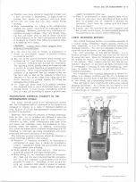
Engine coolant constantly flows through the heater core
during engine operation. Heater output is adjusted by
varying the airflow and air temperature through the sys
tem. A dash mounted three lever control system is em
ployed. One lever controls the heater-defroster air
deflector. The second lever opens the air door and op
erates the three speed fan switch. The third lever oper
ates a temperature door which passes the airflow either
through the heater core, around the core, or partially
through and partially around the core.
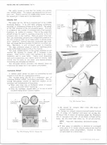
CONTROLS
The heater controls are located in the center of the
dash, below the ash tray. In operation, three levers con
trol all heater operations (fig. 2).
system. Moving the lever to the right about one-third of
its travel opens the air door in the air distributor duct.
Moving the lever further to the right operates the three
speed blower switch.
DEF Lever
Moving the DEF (defroster) lever to the right moves
an air deflector in the distributor duct which channels the
airflow partially or fully to the defroster air outlets.
AIR-FAN Lever
When this lever is fully left, no air passes through the
HEAT Lever
When this lever is fully left, the temperature door in
the blower duct causes the airflow to bypass the heater
core. Moving the lever to the right moves the tempera
ture door allowing some air to pass through the core and
some to bypass the core. With the lever fully right, all
air flowing through the system passes through the core.
COMPONENT REPLACEMENT A N D REPAIR
BLOWER ASSEMBLY
Removal
1. Disconnect battery ground cable.
2. Support the right front of the hood in the fully raised
position.
3. Carefully scribe the hood and fender locations of the
right hood hinge and remove the hinge.
4. Unclip the blower wire at the blower flange terminal
and note or mark the motor flange position in rela
tion to the blower case.
5. Remove the blower assembly mounting screws.
6. Remove the blower assembly (pry the flange away
from the case carefully if the sealer acts as an ad
hesive).
7. Remove the nut attaching the blower wheel to the
motor shaft and separate the assembly.
Installation
1. Assemble the blower wheel to the motor with the
open end of the blower away from the motor.
2. Install the assembly to the blower case, connect
ground strap, and connect the motor wire.
3. Remount the hood hinge aligning it carefully with the
scribed lines. Check hood alignment.
4. Connect battery ground cable.
BLOWER, CORE CASE A N D CORE ASSEMBLY
Removal (Fig. 3)
1. Drain radiator.
2. Disconnect battery ground cable.
3. Unclip the blower motor wire at the blower flange
terminal.
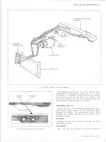
4. Disconnect heater hoses at the core tubes (fig. 4).
5. (Under dash) Remove the seal on the termperature
door cable at the distributor duct adapter and dis
connect the cable from the temperature door.
6. In order to gain access to the lower outboard case
attachments, the right front fender skirt should be
loosened and moved,, Remove enough skirt mounting
screws and bolts (from the rear forward) to move the
skirt a sufficient amount.
7. Support the right front of the hood in the fully raised
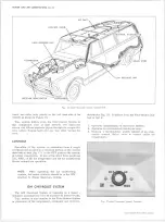
Fig. 3 — Heater Assembly
10-30 CHEVROLET TRUCK SERVICE MANUAL
Содержание 10 1971 Series
Страница 1: ......
Страница 96: ......
Страница 100: ...10 30 CHEVROLET TRUCK SERVICE MANUAL Fig 4 10 30 Series Truck Frame FRAME 2 4 ...
Страница 120: ......
Страница 203: ...ENGINE 6 25 Fig 22L Engine Mounts 10 30 CHEVROLET TRUCK SERVICE MANUAL ...
Страница 215: ...ENGINE 6 37 REAR M O U NT Fig 21V Engine Mounts 10 30 CHEVROLET TRUCK SERVICE MANUAL ...
Страница 218: ......
Страница 249: ......
Страница 250: ...EMISSION CONTROL SYSTEMS 6T 4 Fig 3 Combination Emission Control System Routing V8 10 30 CHEVROLET TRUCK SERVICE MANUAL ...
Страница 324: ......
Страница 339: ...FUEL TANK AND EXHAUST SYSTEMS 8 15 SPECIAL TOOLS Fig 22 Special Tools 1 J 23346 Fuel Tank Gauge Remover and Installer ...
Страница 340: ......
Страница 365: ...10 30 CHEVROLET TRUCK SERVICE MANUAL Fig 43 Power Steering Pump M ounting STEERING 9 25 ...
Страница 368: ......
Страница 386: ......
Страница 390: ...ELECTRICAL BODY AND CHASSIS 12 4 10 30 CHEVROLET TRUCK SERVICE MANUAL ...
Страница 391: ......
Страница 392: ...ELECTRICAL BODY AND CHASSIS 12 6 Fig 5 Rear Lighting Composite 10 30 CHEVROLET TRUCK SERVICE MANUAL ...
Страница 409: ...ELECTRICAL BODY AND CHASSIS 12 23 Fig 27 Engine Compartment CA30 02 10 30 CHEVROLET TRUCK SERVICE MANUAL ...
Страница 410: ...ELECTRICAL BODY AND CHASSIS 12 24 18DK GRN 19 Fig 28 Instrument Panel CA30 02 10 30 CHEVROLET TRUCK SERVICE MANUAL ...
Страница 411: ...ELECTRICAL BODY AND CHASSIS 12 25 Fig 29 Instrument Panel CA30 02 10 30 CHEVROLET TRUCK SERVICE MANUAL ...
Страница 412: ...ELECTRICAL BODY AND CHASSIS 12 26 fh Ar r kk 4 Fig 30 Engine Compartment C A K A 10 20 CA30 03 z _ ...
Страница 416: ...ELECTRICAL BODY AND CHASSIS 12 30 Fig 34 Engine Compartment CA KA10 20 CA30 04 10 30 CHEVROLET TRUCK SERVICE MANUAL ...
Страница 420: ...ELECTRICAL BODY AND CHASSIS 12 34 Fig 38 Engine Compartment C A K A 1 0 20 06 16 10 30 CHEVROLET TRUCK SERVICE MANUAL ...
Страница 422: ...ELECTRICAL BODY AND CHASSIS 12 36 Fig 40 Instrument Panel C A K A 10 20 06 16 10 30 CHEVROLET TRUCK SERVICE MANUAL ...
Страница 423: ...ELECTRICAL BODY AND CHASSIS 12 37 Fig 41 R ear Lamps C A K A 1 0 20 06 16 10 30 CHEVROLET TRUCK SERVICE MANUAL ...
Страница 424: ...ELECTRICAL BODY AND CHASSIS 12 38 Fig 42 Engine Compartment CA KA10 20 CAl30 14 34 10 30 CHEVROLET TRUCK SERVICE MANUAL ...
Страница 426: ...ELECTRICAL BODY AND CHASSIS 12 40 Fig 44 Instrument Panel CA KA10 20 CA30 14 34 10 30 CHEVROLET TRUCK SERVICE MANUAL ...
Страница 428: ......
Страница 432: ......
Страница 449: ...SPECIFICATIONS 9 10 30 CHEVROLET TRUCK SERVICE MANUAL ...
Страница 463: ......
Страница 464: ......
Страница 465: ......
Страница 466: ......