


HEATER AND AIR CONDITIONING 1A-23
add the same amount of new refrigerant oil to the
replacement compressor.
b. If the quantity drained was less than 4 fluid oz.,
add 6 fluid oz. of new refrigeration oil to the
replacement compressor.
c. If a new service compressor is being installed,
drain all oil from it and replace only the amount
specified in Steps 3a and 3b above.
d. If a field repaired compressor is being installed,
add an additional 1 fluid oz. to the compressor.
4. In the event that it is not possible to idle the com
pressor as outlined in Step 1 to effect oil return to
it, proceed as follows:
a. Remove the compressor, drain, measure and
discard the oil.
b. If the amount drained is more than 1-1/2 fluid
oz. and the system shows no signs of a major
leak, add the same amount to the replacement
compressor.
c. If the amount drained is less than 1-1/2 oz. and
COMPONENT REPLACEMENT
ALL SYSTEMS
PREPARING SYSTEM FOR
REPLACEMENT OF CO M PO NEN T PARTS
Air conditioning, like many other things, is fairly simple
to service once it is understood. However, there are
certain procedures, practices and precautions that should
be followed to prevent costly repairs, personal injury
or damage to equipment. For this reason it is strongly
recommended that the preceding information in this sec
tion be studied thoroughly before attempting to service
the system.
Great emphasis must be placed upon keeping the sys
tem clean.
Use plugs or caps to close system com
ponents and hoses when they are opened to the atmos
phere. Keep your work area clean.
In removing and replacing any part which requires
unsealing the refrigerant circuit the following operations,
which are described in this section, must be performed
in the sequence shown.
1. Purge the system by releasing the refrigerant to the
atmosphere.
2. Remove and replace the defective part.
3. Evacuate and charge the system.
CAUTION:
Always wear protective goggles
when working on refrigeration systems. Goggles
J-5453 are included in the set of air conditioning
special tools.
Also, beware of the danger of
carbon monoxide fumes by avoiding running the
engine in closed or improperly ventilated
garages.
FOREIGN MATERIAL IN THE SYSTEM
Whenever foreign material is found in the system, it
must be removed before restoring the system to opera
tion.
In the case of compressor mechanical failure, per
form the following operations:
1. Remove the compressor.
2. Remove the receiver-dehydrator and discard the unit.
3. Flush the condenser to remove foreign material
which has been pumped into it.
the system appears to have lost an excessive
amount of oil, add 6 fluid oz. of clean refrigera
tion oil to replacement compressor, 7 fluid oz. to
a repaired compressor.
If the oil contains chips or other foreign ma
terial, replace the receiver-dehydrator and flush
or replace all component parts as necessary. Add
the full 11 fluid oz. of new refrigeration oil to the
replacement compressor.
5. Add additional oil in the following amounts for any
system components being replaced.
Evaporator Core..................................
3 fluid oz.
Condenser............................................
1 fluid oz.
Receiver-Dehydrator...........................
1 fluid oz.
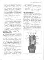
NOTE:
When adding oil to the compressor, it
will be necessary to tilt the rear end of the
compressor up so that the oil will not run out
of the suction and discharge ports. Do not set
the compressor on the shaft end.
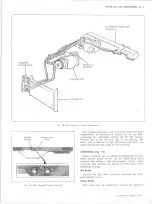
A N D M IN O R REPAIR
Disconnect the line from the receiver-dehydrator
at the inlet connection of the expansion valve. Inspect
the inlet screen for the presence of metal chips or
other foreign material.
If the screen is plugged,
replace it.
Reconnect the line to the expansion
valve.
5. Install a new receiver-dehydrator.
6. Install the replacement compressor.
7. Add the necessary quantity of oil to the system (one
fluid ounce because of receiver-dehydrator replace
ment plus the quantity needed for the replacement
compressor -
see "Checking Compressor Oil
Charge" under "Checking Oil."
8. Evacuate and charge the system.
9. Check system performance.
REFRIGERANT LINE CO NNECTIO NS
“O ” Rings
Always replace the "O" ring when a connection has
been broken. When replacing the "O" ring, first dip it
in clean refrigeration oil. Always use a backing wrench
on "O" ring fittings to prevent the pipe from twisting and
damaging the "O" ring. Do not overtighten. Correct
torque specifications are as follows:
Metal
Tube
O.D.
Thread and
Fitting
Size
Steel
Tubing
Torque*
Alum.
Tubing
Torque*
1/4
7/16
13
6
3/8
5/8
33
12
1/2
3/4
33
12
5/8
7/8
33
20
3/4
1-1/16
33
25
*Foot Pounds.
NOTE:
Where steel to aluminum connections
are being made, use torque for aluminum tubing.
Hose Clamps
When hose clamp connections are encounted, special
10-30 CHEVROLET TRUCK SERVICE MANUAL
Содержание 10 1971 Series
Страница 1: ......
Страница 96: ......
Страница 100: ...10 30 CHEVROLET TRUCK SERVICE MANUAL Fig 4 10 30 Series Truck Frame FRAME 2 4 ...
Страница 120: ......
Страница 203: ...ENGINE 6 25 Fig 22L Engine Mounts 10 30 CHEVROLET TRUCK SERVICE MANUAL ...
Страница 215: ...ENGINE 6 37 REAR M O U NT Fig 21V Engine Mounts 10 30 CHEVROLET TRUCK SERVICE MANUAL ...
Страница 218: ......
Страница 249: ......
Страница 250: ...EMISSION CONTROL SYSTEMS 6T 4 Fig 3 Combination Emission Control System Routing V8 10 30 CHEVROLET TRUCK SERVICE MANUAL ...
Страница 324: ......
Страница 339: ...FUEL TANK AND EXHAUST SYSTEMS 8 15 SPECIAL TOOLS Fig 22 Special Tools 1 J 23346 Fuel Tank Gauge Remover and Installer ...
Страница 340: ......
Страница 365: ...10 30 CHEVROLET TRUCK SERVICE MANUAL Fig 43 Power Steering Pump M ounting STEERING 9 25 ...
Страница 368: ......
Страница 386: ......
Страница 390: ...ELECTRICAL BODY AND CHASSIS 12 4 10 30 CHEVROLET TRUCK SERVICE MANUAL ...
Страница 391: ......
Страница 392: ...ELECTRICAL BODY AND CHASSIS 12 6 Fig 5 Rear Lighting Composite 10 30 CHEVROLET TRUCK SERVICE MANUAL ...
Страница 409: ...ELECTRICAL BODY AND CHASSIS 12 23 Fig 27 Engine Compartment CA30 02 10 30 CHEVROLET TRUCK SERVICE MANUAL ...
Страница 410: ...ELECTRICAL BODY AND CHASSIS 12 24 18DK GRN 19 Fig 28 Instrument Panel CA30 02 10 30 CHEVROLET TRUCK SERVICE MANUAL ...
Страница 411: ...ELECTRICAL BODY AND CHASSIS 12 25 Fig 29 Instrument Panel CA30 02 10 30 CHEVROLET TRUCK SERVICE MANUAL ...
Страница 412: ...ELECTRICAL BODY AND CHASSIS 12 26 fh Ar r kk 4 Fig 30 Engine Compartment C A K A 10 20 CA30 03 z _ ...
Страница 416: ...ELECTRICAL BODY AND CHASSIS 12 30 Fig 34 Engine Compartment CA KA10 20 CA30 04 10 30 CHEVROLET TRUCK SERVICE MANUAL ...
Страница 420: ...ELECTRICAL BODY AND CHASSIS 12 34 Fig 38 Engine Compartment C A K A 1 0 20 06 16 10 30 CHEVROLET TRUCK SERVICE MANUAL ...
Страница 422: ...ELECTRICAL BODY AND CHASSIS 12 36 Fig 40 Instrument Panel C A K A 10 20 06 16 10 30 CHEVROLET TRUCK SERVICE MANUAL ...
Страница 423: ...ELECTRICAL BODY AND CHASSIS 12 37 Fig 41 R ear Lamps C A K A 1 0 20 06 16 10 30 CHEVROLET TRUCK SERVICE MANUAL ...
Страница 424: ...ELECTRICAL BODY AND CHASSIS 12 38 Fig 42 Engine Compartment CA KA10 20 CAl30 14 34 10 30 CHEVROLET TRUCK SERVICE MANUAL ...
Страница 426: ...ELECTRICAL BODY AND CHASSIS 12 40 Fig 44 Instrument Panel CA KA10 20 CA30 14 34 10 30 CHEVROLET TRUCK SERVICE MANUAL ...
Страница 428: ......
Страница 432: ......
Страница 449: ...SPECIFICATIONS 9 10 30 CHEVROLET TRUCK SERVICE MANUAL ...
Страница 463: ......
Страница 464: ......
Страница 465: ......
Страница 466: ......