


HEATER AND AIR CONDITIONING 1A-15
• A five ampere time delay cartridge fuse has been
installed in the common line to protect the windings
of the compressor.
The fuse will blow if an ex
cessive load is placed on the pump. In the event the
fuse is blown, replace with a five ampere time delay
fuse - do not use a substitute fuse as it will result in
damage to the starting windings.
• If the pump is being utilized to evacuate a burnt-out
system, a filter must be connected to the intake
fitting to prevent any sludge from contaminating the
working parts, which will result in malfunction of the
pump.
• Do not use the vacuum pump as an air compressor.
LEAK TESTING THE SYSTEM
Whenever a refrigerant leak is suspected in the system
or a service operation performed which results in dis
turbing lines or connections, it is advisable to test for
leaks. Common sense should be the governing factor in
performing any leak test, since the necessity and extent
of any such test will, in general, depend upon the nature
of the complaint and the type of service performed on the
system.
NOTE:
The use of a leak detecting dye within
the system is not recommended because of the
following reasons:
1. Refrigerant leakage can exist without any oil leakage.
In this case the dye will not indicate the leak, how
ever, a torch detector will.
2. The addition of additives, other than inhibitors, may
alter the stability of the refrigeration system and
cause malfunctions.
3. Dye type leak detectors, which are insoluble, form a
curdle which can block the inlet screen of the ex
pansion valve.
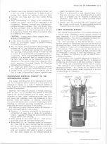
Leak Detector
Tool J-6084 (fig. 24) is a propane gas-burning torch
which is used to locate a leak in any part of the system.
Refrigerant gas drawn into the sampling tube attached to
the torch will cause the torch flame to change color in
proportion to the size of the leak.
Propane gas fuel
cylinders used with the torch are readily available com
mercially throughout the country.
CAUTION:
Do not use lighted detector in any
place where combustible or explosive gases,
dusts or vapors may be present.
Operating Detector
1. Determine if there is sufficient refrigerant in the
system for leak testing.
2. Open control valve only until a low hiss of gas is
heard, then light gas at opening in chimney.
3. Adjust flame until desired volume is obtained. This
is most satisfactory when blue flame is approxi
mately 3/8” above reactor plate. The reactor plate
will quickly heat to a cherry red.
4. Explore for leaks by moving the end of the sampling
hose around possible leak points in the system. Do
not pinch or kink hose.
NOTE:
Since R-12 is heavier than air, it is
good practice to place open end of sampling tube
Fig. 24—-Leak Detector
immediately below point being tested, particu
larly in cases of small leaks.
CAUTION:
Do_ not breathe the fumes that are
produced by the burning R-12 gas in the de
tector flame, since such fumes can be toxic in
large concentrations of R-12.
5. Watch for color changes.
The color of the flame
which passes through the reaction plate will change
to green or yellow-green when sampling hose draws
in very small leaks of R-12. Large leaks will be
indicated by a change in color to a brilliant blue or
purple. When the sampling hose passes the leak,
the flame will clear to an almost colorless pale
blue again. Observations are best made in a semi
darkened area. If the flame remains yellow when
unit is removed from leak, insufficient air is being
drawn in or the reactor plate is dirty.
NOTE:
A refrigerant leak in the high pressure
side of the system may be more easily detected
if the system is operated for a few minutes,
then shut off and checked immediately (before
system pressures equalize). A leak on the low
pressure side may be more easily detected after
the engine has been shut off for several minutes
(system pressures equalized); this applies par
ticularly to the front seal.
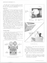
AVAILABILITY OF REFRIGERANT-12
Refrigerant 12 is available in 30 lb. and in 15 oz. dis
posable containers.
Normally, air conditioning systems are charged making
use of the J-8393 Charging Station which uses the 30 lb-
container.
Evacuating and Charging Procedures are
noted later in this section.
The 15 oz. disposable cans are generally used for
miscellaneous operations such as flushing.
10-30 CHEVROLET TRUCK SERVICE MANUAL
Содержание 10 1971 Series
Страница 1: ......
Страница 96: ......
Страница 100: ...10 30 CHEVROLET TRUCK SERVICE MANUAL Fig 4 10 30 Series Truck Frame FRAME 2 4 ...
Страница 120: ......
Страница 203: ...ENGINE 6 25 Fig 22L Engine Mounts 10 30 CHEVROLET TRUCK SERVICE MANUAL ...
Страница 215: ...ENGINE 6 37 REAR M O U NT Fig 21V Engine Mounts 10 30 CHEVROLET TRUCK SERVICE MANUAL ...
Страница 218: ......
Страница 249: ......
Страница 250: ...EMISSION CONTROL SYSTEMS 6T 4 Fig 3 Combination Emission Control System Routing V8 10 30 CHEVROLET TRUCK SERVICE MANUAL ...
Страница 324: ......
Страница 339: ...FUEL TANK AND EXHAUST SYSTEMS 8 15 SPECIAL TOOLS Fig 22 Special Tools 1 J 23346 Fuel Tank Gauge Remover and Installer ...
Страница 340: ......
Страница 365: ...10 30 CHEVROLET TRUCK SERVICE MANUAL Fig 43 Power Steering Pump M ounting STEERING 9 25 ...
Страница 368: ......
Страница 386: ......
Страница 390: ...ELECTRICAL BODY AND CHASSIS 12 4 10 30 CHEVROLET TRUCK SERVICE MANUAL ...
Страница 391: ......
Страница 392: ...ELECTRICAL BODY AND CHASSIS 12 6 Fig 5 Rear Lighting Composite 10 30 CHEVROLET TRUCK SERVICE MANUAL ...
Страница 409: ...ELECTRICAL BODY AND CHASSIS 12 23 Fig 27 Engine Compartment CA30 02 10 30 CHEVROLET TRUCK SERVICE MANUAL ...
Страница 410: ...ELECTRICAL BODY AND CHASSIS 12 24 18DK GRN 19 Fig 28 Instrument Panel CA30 02 10 30 CHEVROLET TRUCK SERVICE MANUAL ...
Страница 411: ...ELECTRICAL BODY AND CHASSIS 12 25 Fig 29 Instrument Panel CA30 02 10 30 CHEVROLET TRUCK SERVICE MANUAL ...
Страница 412: ...ELECTRICAL BODY AND CHASSIS 12 26 fh Ar r kk 4 Fig 30 Engine Compartment C A K A 10 20 CA30 03 z _ ...
Страница 416: ...ELECTRICAL BODY AND CHASSIS 12 30 Fig 34 Engine Compartment CA KA10 20 CA30 04 10 30 CHEVROLET TRUCK SERVICE MANUAL ...
Страница 420: ...ELECTRICAL BODY AND CHASSIS 12 34 Fig 38 Engine Compartment C A K A 1 0 20 06 16 10 30 CHEVROLET TRUCK SERVICE MANUAL ...
Страница 422: ...ELECTRICAL BODY AND CHASSIS 12 36 Fig 40 Instrument Panel C A K A 10 20 06 16 10 30 CHEVROLET TRUCK SERVICE MANUAL ...
Страница 423: ...ELECTRICAL BODY AND CHASSIS 12 37 Fig 41 R ear Lamps C A K A 1 0 20 06 16 10 30 CHEVROLET TRUCK SERVICE MANUAL ...
Страница 424: ...ELECTRICAL BODY AND CHASSIS 12 38 Fig 42 Engine Compartment CA KA10 20 CAl30 14 34 10 30 CHEVROLET TRUCK SERVICE MANUAL ...
Страница 426: ...ELECTRICAL BODY AND CHASSIS 12 40 Fig 44 Instrument Panel CA KA10 20 CA30 14 34 10 30 CHEVROLET TRUCK SERVICE MANUAL ...
Страница 428: ......
Страница 432: ......
Страница 449: ...SPECIFICATIONS 9 10 30 CHEVROLET TRUCK SERVICE MANUAL ...
Страница 463: ......
Страница 464: ......
Страница 465: ......
Страница 466: ......