


HEATER AND AIR CONDITIONING 1A-18
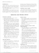
G M Chevrolet Air Conditioning
(Refrigerant Charge - 3 lbs.-4 oz.)
Temperature of
Air Entering
Condenser
70°
80°
90°
100°
110°
120°
Engine rpm
2000
Compressor
Head Pressure*
110-
120
135-
145
160-
170
190-
200
220-
230
260-
270
Suction Pres
sure psi*
6
7
9
10
10
13
Discharge Air
Temperature*
40-
45
41-
46
41-
46
42-
47
44-
49
44-
49
*When compressor clutch disengages.
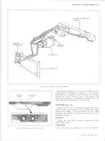
EVAPORATOR CONTROL VALVE (POA) (Fig. 26)
The only check for proper POA valve operation is to
check the suction pressure at the valve during a per
formance test. The POA valve is an absolute valve and
will provide different gauge readings based on the alti
tude where the readings are being taken. Correct gauge
reading at sea level is 29.5 psig. Gauge readings will
be one-half psi higher for each additional 1000 feet of
elevation.
The following table lists gauge readings at
different altitudes.
If a valve gives improper gauge
readings, it must be replaced since it is not repairable
or adjustable.
29.5 psig. — Sea Level
30.0 psig. — 1000 ft.
30.5 psig. — 2000 ft.
31.0 psig. — 3000 ft.
31.5 psig. — 4000 ft.
32.0 psig. — 5000 ft.
32.5 psig. — 6000 ft.
33.0 psig. — 7000 ft.
33.5 psig. -- 8000 ft.
34.0 psig. — 9000 ft.
34.5 psig. — 10000 ft.
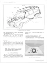
THERMOSTATIC SWITCH
Roof-Mounted and G M Chevrolet Systems
These systems make use of a thermostatic switch with
an air sensing capillary.
This capillary controls the
switch by sensing the temperature of the air leaving the
fins (fig. 27).
Checking for Proper Operation
1. Install the gauge set and set up the vehicle as des-
scribed under "Performance Test."
2. Movement of the temperature control knob should
result in a definite change in suction pressure and
cycling of the compressor clutch.
• If compressor continued to operate regardless of
the knob adjustment, it indicates that the switch
points are fused which will lead to evaporator
freeze-up. Replace the switch.
• If the compressor does not operate, regardless of
the position of the knob, a loss of the power element
OUTLET
Fig. 26— Evaporator Pressure Control Valve (P O A )
charge is indicated (provided that it has been estab
lished that power is supplied to the switch). This,
of course, results in no cooling. Replace the switch.
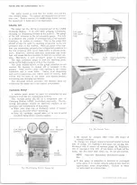
THERMOSTATIC SWITCH
THERMOSTATIC
BLOWER
CAPILLARY INSTALLED
SWITCH
SWITCH
IN BRACKET
G M CHEVROLET SYSTEM
Fig. 2 7 — Thermostatic Sw itch Installation
10-30 CHEVROLET TRUCK SERVICE MANUAL
Содержание 10 1971 Series
Страница 1: ......
Страница 96: ......
Страница 100: ...10 30 CHEVROLET TRUCK SERVICE MANUAL Fig 4 10 30 Series Truck Frame FRAME 2 4 ...
Страница 120: ......
Страница 203: ...ENGINE 6 25 Fig 22L Engine Mounts 10 30 CHEVROLET TRUCK SERVICE MANUAL ...
Страница 215: ...ENGINE 6 37 REAR M O U NT Fig 21V Engine Mounts 10 30 CHEVROLET TRUCK SERVICE MANUAL ...
Страница 218: ......
Страница 249: ......
Страница 250: ...EMISSION CONTROL SYSTEMS 6T 4 Fig 3 Combination Emission Control System Routing V8 10 30 CHEVROLET TRUCK SERVICE MANUAL ...
Страница 324: ......
Страница 339: ...FUEL TANK AND EXHAUST SYSTEMS 8 15 SPECIAL TOOLS Fig 22 Special Tools 1 J 23346 Fuel Tank Gauge Remover and Installer ...
Страница 340: ......
Страница 365: ...10 30 CHEVROLET TRUCK SERVICE MANUAL Fig 43 Power Steering Pump M ounting STEERING 9 25 ...
Страница 368: ......
Страница 386: ......
Страница 390: ...ELECTRICAL BODY AND CHASSIS 12 4 10 30 CHEVROLET TRUCK SERVICE MANUAL ...
Страница 391: ......
Страница 392: ...ELECTRICAL BODY AND CHASSIS 12 6 Fig 5 Rear Lighting Composite 10 30 CHEVROLET TRUCK SERVICE MANUAL ...
Страница 409: ...ELECTRICAL BODY AND CHASSIS 12 23 Fig 27 Engine Compartment CA30 02 10 30 CHEVROLET TRUCK SERVICE MANUAL ...
Страница 410: ...ELECTRICAL BODY AND CHASSIS 12 24 18DK GRN 19 Fig 28 Instrument Panel CA30 02 10 30 CHEVROLET TRUCK SERVICE MANUAL ...
Страница 411: ...ELECTRICAL BODY AND CHASSIS 12 25 Fig 29 Instrument Panel CA30 02 10 30 CHEVROLET TRUCK SERVICE MANUAL ...
Страница 412: ...ELECTRICAL BODY AND CHASSIS 12 26 fh Ar r kk 4 Fig 30 Engine Compartment C A K A 10 20 CA30 03 z _ ...
Страница 416: ...ELECTRICAL BODY AND CHASSIS 12 30 Fig 34 Engine Compartment CA KA10 20 CA30 04 10 30 CHEVROLET TRUCK SERVICE MANUAL ...
Страница 420: ...ELECTRICAL BODY AND CHASSIS 12 34 Fig 38 Engine Compartment C A K A 1 0 20 06 16 10 30 CHEVROLET TRUCK SERVICE MANUAL ...
Страница 422: ...ELECTRICAL BODY AND CHASSIS 12 36 Fig 40 Instrument Panel C A K A 10 20 06 16 10 30 CHEVROLET TRUCK SERVICE MANUAL ...
Страница 423: ...ELECTRICAL BODY AND CHASSIS 12 37 Fig 41 R ear Lamps C A K A 1 0 20 06 16 10 30 CHEVROLET TRUCK SERVICE MANUAL ...
Страница 424: ...ELECTRICAL BODY AND CHASSIS 12 38 Fig 42 Engine Compartment CA KA10 20 CAl30 14 34 10 30 CHEVROLET TRUCK SERVICE MANUAL ...
Страница 426: ...ELECTRICAL BODY AND CHASSIS 12 40 Fig 44 Instrument Panel CA KA10 20 CA30 14 34 10 30 CHEVROLET TRUCK SERVICE MANUAL ...
Страница 428: ......
Страница 432: ......
Страница 449: ...SPECIFICATIONS 9 10 30 CHEVROLET TRUCK SERVICE MANUAL ...
Страница 463: ......
Страница 464: ......
Страница 465: ......
Страница 466: ......