


HEATER AND AIR CONDITIONING 1A-20
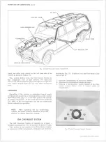
POORLY LOCATED POWER ELEMENT BULB
Normal Pressure.
Poor Cooling.
Check for Defective Valve
The following procedure must be followed to determine
if a malfunction is due to a defective expansion valve.
1. Check to determine if the system will meet the per
formance test as outlined previously. If the expan
sion valve is defective, the low pressure readings
(POA or evaporator pressure) will be above specifi
cation.
2. The loss of system performance is not as evident
when the compressor head pressure is below 200 PSI.
Therefore, it may be necessary to increase the sys
tem head pressure by partially blocking the conden
ser. Disconnect the blower lead wire and repeat the
“ Peformance Check" to determine if the evaporator
pressure can be obtained.
3. The system will also indicate a low refrigerant
charge by bubbles occurring in the sight glass.
Systems equipped with a POA Valve require the
following additional test to determine if the de
ficiency is the expansion valve.
4. Remove the expansion valve bulb from the evaporator
outlet pipe, and the connector on the blower resistor.
Place the blower on "low." With the engine operat
ing at 2,000 rpm, observe the POA gauge pressure.
5. Insert the expansion valve bulb in a cup of ice. This
should result in the POA pressure being reduced
to approximately 30 P.S.I. If the pressure does not
reduce to this level, the POA valve is defective. If
the pressure falls considerably below 30 P.S.I., the
expansion valve is defective.
ENGINE IDLE CO MPENSATOR
This additional aid to prevent stalling during prolonged
hot weather periods is included with all air conditioned
vehicles.
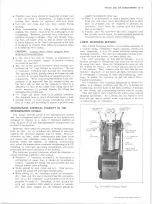
The idle compensator is a thermostatically
controlled air bleed which supplies additional air to the
idle mixture. On V-8 engines, with factory installed air
conditioning systems, the compensator is located within
the carburetor and is accessible when the engine air
cleaner is removed. On all other vehicles the compen
sator is threaded into a manifold fitting below the car
buretor. All compensators are factory set and are non-
adjustable.
A malfunctioning unit should be replaced.
NOTE:
If engine idle is erratic, hold the idle
compensator valve closed with a pencil or
wooden dowel while adjusting the idle mixture
screw(s). Never attempt to bend the bimetal
strip or attempt any valve adjustment.
EVACUATING A N D CH ARG ING PROCEDURES
AIR C O N D IT IO N IN G SYSTEM CAPACITY
Refrigerant
Charge
Oil Charge
Four-Season System 3 lbs. 4 oz.
10 oz. 525 Viscosity
Roof-Mounted
4 lbs. 8 oz.
13 oz. 525 Viscosity
GM Chevrolet
3 lbs. 4 oz.
10 oz. 525 Viscosity
PURGING THE SYSTEM
In replacing any of the air conditioning components the
system must be completely purged or drained of re
frigerant. The purpose is to lower the pressure inside
the system so that a component part can be safely re
moved.
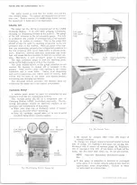
1. With engine stopped, install high and low pressure
lines of Charging Station gauge set to the proper
high and low pressure gauge fittings. (See "Install
ing Charging Station to Check System Operation.")
NOTE:
Before installing lines, be sure that all
four controls on the gauge set are closed.
2. Disconnect vacuum line at Charging Station vacuum
pump and lay end of line on a clean rag on the floor.
3. Crack open high (2) and low (1) pressure control
valves, and allow refrigerant to purge from system.
CAUTION:
Do not open valves too much or
compressor oil may be discharged with the re
frigerant. Oil loss can be easily detected on
rag at discharge line.
EVACUATING A N D C H A R G IN G THE SYSTEM
GENERAL NOTE:
In all evacuating proce
dures shown below, the specification of 26-28
inches of Mercury vacuum is used. These fig
ures are only attainable at or near Sea Level
Elevation. For each 1000 feet above sea level
where this operation is being performed, the
specifications should be lowered by 1 inch. Ex
ample:
at 5000 ft. elevation, only 21 to 23
inches of vacuum can normally be obtained.
Whenever the air conditioning system is open for any
reason, it should not be put into operation again until it
has been evacuated to remove air and moisture which
may have entered the system.
The following procedures are based on the use of the
J-8393 Charging Station.
Filling Charging Cylinder
1. Open valve on bottom of charging cylinder allowing
refrigerant to enter cylinder.
2. Bleed cylinder valve on top (behind control panel) as
required to allow refrigerant to enter. When refrig
erant reaches desired level (see "Air Conditioning
System Capacity"), close valve at bottom of cylinder
and be certain bleed valve is closed securely.
NOTE:
It will be necessary to close bleed
valve periodically to allow boiling to subside to
check level in sight glass.
Evacuating and Charging System
1. Install charging station and purge system as noted
10-30 CHEVROLET TRUCK SERVICE MANUAL
Содержание 10 1971 Series
Страница 1: ......
Страница 96: ......
Страница 100: ...10 30 CHEVROLET TRUCK SERVICE MANUAL Fig 4 10 30 Series Truck Frame FRAME 2 4 ...
Страница 120: ......
Страница 203: ...ENGINE 6 25 Fig 22L Engine Mounts 10 30 CHEVROLET TRUCK SERVICE MANUAL ...
Страница 215: ...ENGINE 6 37 REAR M O U NT Fig 21V Engine Mounts 10 30 CHEVROLET TRUCK SERVICE MANUAL ...
Страница 218: ......
Страница 249: ......
Страница 250: ...EMISSION CONTROL SYSTEMS 6T 4 Fig 3 Combination Emission Control System Routing V8 10 30 CHEVROLET TRUCK SERVICE MANUAL ...
Страница 324: ......
Страница 339: ...FUEL TANK AND EXHAUST SYSTEMS 8 15 SPECIAL TOOLS Fig 22 Special Tools 1 J 23346 Fuel Tank Gauge Remover and Installer ...
Страница 340: ......
Страница 365: ...10 30 CHEVROLET TRUCK SERVICE MANUAL Fig 43 Power Steering Pump M ounting STEERING 9 25 ...
Страница 368: ......
Страница 386: ......
Страница 390: ...ELECTRICAL BODY AND CHASSIS 12 4 10 30 CHEVROLET TRUCK SERVICE MANUAL ...
Страница 391: ......
Страница 392: ...ELECTRICAL BODY AND CHASSIS 12 6 Fig 5 Rear Lighting Composite 10 30 CHEVROLET TRUCK SERVICE MANUAL ...
Страница 409: ...ELECTRICAL BODY AND CHASSIS 12 23 Fig 27 Engine Compartment CA30 02 10 30 CHEVROLET TRUCK SERVICE MANUAL ...
Страница 410: ...ELECTRICAL BODY AND CHASSIS 12 24 18DK GRN 19 Fig 28 Instrument Panel CA30 02 10 30 CHEVROLET TRUCK SERVICE MANUAL ...
Страница 411: ...ELECTRICAL BODY AND CHASSIS 12 25 Fig 29 Instrument Panel CA30 02 10 30 CHEVROLET TRUCK SERVICE MANUAL ...
Страница 412: ...ELECTRICAL BODY AND CHASSIS 12 26 fh Ar r kk 4 Fig 30 Engine Compartment C A K A 10 20 CA30 03 z _ ...
Страница 416: ...ELECTRICAL BODY AND CHASSIS 12 30 Fig 34 Engine Compartment CA KA10 20 CA30 04 10 30 CHEVROLET TRUCK SERVICE MANUAL ...
Страница 420: ...ELECTRICAL BODY AND CHASSIS 12 34 Fig 38 Engine Compartment C A K A 1 0 20 06 16 10 30 CHEVROLET TRUCK SERVICE MANUAL ...
Страница 422: ...ELECTRICAL BODY AND CHASSIS 12 36 Fig 40 Instrument Panel C A K A 10 20 06 16 10 30 CHEVROLET TRUCK SERVICE MANUAL ...
Страница 423: ...ELECTRICAL BODY AND CHASSIS 12 37 Fig 41 R ear Lamps C A K A 1 0 20 06 16 10 30 CHEVROLET TRUCK SERVICE MANUAL ...
Страница 424: ...ELECTRICAL BODY AND CHASSIS 12 38 Fig 42 Engine Compartment CA KA10 20 CAl30 14 34 10 30 CHEVROLET TRUCK SERVICE MANUAL ...
Страница 426: ...ELECTRICAL BODY AND CHASSIS 12 40 Fig 44 Instrument Panel CA KA10 20 CA30 14 34 10 30 CHEVROLET TRUCK SERVICE MANUAL ...
Страница 428: ......
Страница 432: ......
Страница 449: ...SPECIFICATIONS 9 10 30 CHEVROLET TRUCK SERVICE MANUAL ...
Страница 463: ......
Страница 464: ......
Страница 465: ......
Страница 466: ......