


HEATER AND AIR CONDITIONING 1A-12
cooling desired. Fully clockwise at CITY provides maxi
mum cooling; however, turning the knob to HIWAY pro
vides adequate cooling for highway operation.
NOTE:
Reduced cooling could be encountered
when operating at highway speeds with the con
trols at the "CITY" setting.
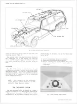
GENERAL IN FO RM ATIO N
In any vocation or trade, there are established proce
dures and practices that have been developed after many
years of experience.
In addition, occupation hazards
may be present that require the observation of certain
precautions or use of special tools and equipment. Ob
serving the procedures, practices and precautions of
servicing refrigeration equipment will greatly reduce the
possibilities of damage to the customers' equipment as
well as virtually eliminate the element of hazard to the
serviceman.
PRECAUTIONS IN HAN DLIN G REFRIGERANT-12
Refrigerant-12 is transparent and colorless in both the
gaseous and liquid state. It has a boiling point of 21.7°F
below zero and, therefore, at all normal temperatures
and pressures it will be a vapor. The vapor is heavier
than air and is noninflammable, nonexplosive, nonpoi-
sonous (except when in contact with an open flame) and
noncorrosive (except when in contact with water). The
following precautions in handling R-12 should be ob
served at all times.
• If it is ever necessary to transport or carry a cylin
der or can of refrigerant in a car, keep it in the
luggage compartment. Refrigerant should not be ex-
’ posed to the radiant heat from the sun since the
resulting increase in pressure may cause the safety
valve to release or the cylinder or can to burst.
• Cylinders or disposable cans should never be sub
jected to high temperature when adding refrigerant
to the system. In most instances, heating the cylin
der or can is required to raise the pressure in the
container higher than the pressure in the system
during the operation. It would be unwise to place the
cylinder on a gas stove, radiator or use a blow torch
while preparing for the charging operation, since a
serious accident could result. Don’t depend on the
safety valve - many cylinders have burst when the
safety valve failed. Remember, high pressure means
that great forces are being exerted against the walls
of the container. A bucket of warm water, not over
125°F, or warm wet rags around the container is all
the heat that is required.
• Do not weld or steam clean on or near the system.
Welding or steam cleaning can result in a dangerous
pressure buildup in the system.
• Discharging large quantities of R-12 into a room can
usually be done safely as the vapor would produce
no ill effects; however, in the event of an accidental
rapid discharge of the system, it is recommended
that inhalation of large quantities of R-12 be avoided.
This caution is especially important if the area con
tains a flame producing device such as a gas heater.
While R-12 normally is nonpoisonous, heavy con
centrations of it in contact with a live flame will
produce a toxic gas. The same gas will also attack
all bright metal surfaces.
• Protection of the eyes is of vital importance! When
working around a refrigerating system, an accident
may cause liquid refrigerant to hit the face. If the
eyes are protected with goggles or glasses, no
serious damage can result.
Just remember, any
R-12 liquid that you can touch or that touches you is
at least 21.7°F, below zero. If a R-12 liquid should
strike the eyes, here is what to do:
1. Keep calm.
2. Do not rub the eyes'. Splash the affected area with
quantities of cold water to gradually get the tem
perature above the freezing point. The use of min
eral, cod liver or an antiseptic oil is important in
providing a protective film to reduce the possibility
of infection.
3. As soon as possible, call or consult an eye specialist
for immediate and future treatment.
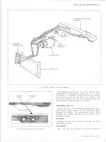
PRECAUTIONS IN H AN DLIN G REFRIGERANT LINES
• All metal tubing lines should be free of kinks, be
cause of the restriction that kinks will offer to the
flow of refrigerant. The refrigeration capacity of the
entire system can be greatly reduced by a single
kink.
• The flexible hose lines should never be bent to a
radius of less than 10 times the diameter of the hose.
• The flexible hose lines should never be allowed to
come within a distance of 2-1/2" of the exhaust
manifold.
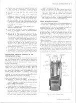
Fig. 2 0 — System Contaminants
10-30 CHEVROLET TRUCK SERVICE MANUAL
Содержание 10 1971 Series
Страница 1: ......
Страница 96: ......
Страница 100: ...10 30 CHEVROLET TRUCK SERVICE MANUAL Fig 4 10 30 Series Truck Frame FRAME 2 4 ...
Страница 120: ......
Страница 203: ...ENGINE 6 25 Fig 22L Engine Mounts 10 30 CHEVROLET TRUCK SERVICE MANUAL ...
Страница 215: ...ENGINE 6 37 REAR M O U NT Fig 21V Engine Mounts 10 30 CHEVROLET TRUCK SERVICE MANUAL ...
Страница 218: ......
Страница 249: ......
Страница 250: ...EMISSION CONTROL SYSTEMS 6T 4 Fig 3 Combination Emission Control System Routing V8 10 30 CHEVROLET TRUCK SERVICE MANUAL ...
Страница 324: ......
Страница 339: ...FUEL TANK AND EXHAUST SYSTEMS 8 15 SPECIAL TOOLS Fig 22 Special Tools 1 J 23346 Fuel Tank Gauge Remover and Installer ...
Страница 340: ......
Страница 365: ...10 30 CHEVROLET TRUCK SERVICE MANUAL Fig 43 Power Steering Pump M ounting STEERING 9 25 ...
Страница 368: ......
Страница 386: ......
Страница 390: ...ELECTRICAL BODY AND CHASSIS 12 4 10 30 CHEVROLET TRUCK SERVICE MANUAL ...
Страница 391: ......
Страница 392: ...ELECTRICAL BODY AND CHASSIS 12 6 Fig 5 Rear Lighting Composite 10 30 CHEVROLET TRUCK SERVICE MANUAL ...
Страница 409: ...ELECTRICAL BODY AND CHASSIS 12 23 Fig 27 Engine Compartment CA30 02 10 30 CHEVROLET TRUCK SERVICE MANUAL ...
Страница 410: ...ELECTRICAL BODY AND CHASSIS 12 24 18DK GRN 19 Fig 28 Instrument Panel CA30 02 10 30 CHEVROLET TRUCK SERVICE MANUAL ...
Страница 411: ...ELECTRICAL BODY AND CHASSIS 12 25 Fig 29 Instrument Panel CA30 02 10 30 CHEVROLET TRUCK SERVICE MANUAL ...
Страница 412: ...ELECTRICAL BODY AND CHASSIS 12 26 fh Ar r kk 4 Fig 30 Engine Compartment C A K A 10 20 CA30 03 z _ ...
Страница 416: ...ELECTRICAL BODY AND CHASSIS 12 30 Fig 34 Engine Compartment CA KA10 20 CA30 04 10 30 CHEVROLET TRUCK SERVICE MANUAL ...
Страница 420: ...ELECTRICAL BODY AND CHASSIS 12 34 Fig 38 Engine Compartment C A K A 1 0 20 06 16 10 30 CHEVROLET TRUCK SERVICE MANUAL ...
Страница 422: ...ELECTRICAL BODY AND CHASSIS 12 36 Fig 40 Instrument Panel C A K A 10 20 06 16 10 30 CHEVROLET TRUCK SERVICE MANUAL ...
Страница 423: ...ELECTRICAL BODY AND CHASSIS 12 37 Fig 41 R ear Lamps C A K A 1 0 20 06 16 10 30 CHEVROLET TRUCK SERVICE MANUAL ...
Страница 424: ...ELECTRICAL BODY AND CHASSIS 12 38 Fig 42 Engine Compartment CA KA10 20 CAl30 14 34 10 30 CHEVROLET TRUCK SERVICE MANUAL ...
Страница 426: ...ELECTRICAL BODY AND CHASSIS 12 40 Fig 44 Instrument Panel CA KA10 20 CA30 14 34 10 30 CHEVROLET TRUCK SERVICE MANUAL ...
Страница 428: ......
Страница 432: ......
Страница 449: ...SPECIFICATIONS 9 10 30 CHEVROLET TRUCK SERVICE MANUAL ...
Страница 463: ......
Страница 464: ......
Страница 465: ......
Страница 466: ......