


HEATER AND AIR CONDITIONING 1A-9
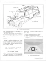
Fig. 15— Four Season System Components
cooler air, moving the lever toward COOL will send
some air through the evaporator core (inoperative when
the OUTLETS lever is set for heater operation) which in
effect bypasses the heater core resulting in less heat
output.
Air Control Lever
When the control is properly adjusted, full left position
("INSIDE") will supply 100% recirculated inside air, and
moving the lever to the word "OUTSIDE" will supply
100% outside air to the system. Lever movement con
trols a vacuum switch which in turn actuates an air inlet
door in the plenum below the air inlet grille and a recir
culating air door in the kick pad. In the full left position,
vacuum also closes the Hot Water Shut Off Valve, pre
venting coolant flow through the heater core.
Defroster
As the Air control knob is moved to the right from the
"OUTSIDE" position toward the word DEFROSTER the
diverter door within the distributor duct moves to send a
portion of the airflow to the defroster ducts. Full "right"
position of the AIR knob, as indicated on the panel, is the
DE-ICE position which sends the total airflow to the
defroster ducts.
Fan Switch
The fan switch controls the operation of the three
speed blower motor.
ROOF MOUNTED SYSTEM
The Roof-Mounted System is available for CK10-20
series Suburban Carryall Trucks.
This system is similar to the Four-Season System in
placement of the compressor, condenser and receiver-
dehydrator (fig. 16). It differs from the Four-Season Sys
tem in that it:
1. Operates independently of the heater system.
2. Operates on recirculated (inside) air only.
3. Utilizes a thermostatic switch instead of an evapora
tor control (POA) valve to control outlet air temper
ature.
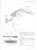
The roof-mounted system incorporates a blower evap
orator unit which is mounted to the inner roof panel at the
rear of the vehicle. An overhead central air distributor
duct, which contains adjustable outlets, extends forward
from the blower-evaporator unit to the windshield header
panel. The refrigerant lines are routed from the engine
compartment to the blower-evaporator unit between the
10-30 CHEVROLET TRUCK SERVICE MANUAL
Содержание 10 1971 Series
Страница 1: ......
Страница 96: ......
Страница 100: ...10 30 CHEVROLET TRUCK SERVICE MANUAL Fig 4 10 30 Series Truck Frame FRAME 2 4 ...
Страница 120: ......
Страница 203: ...ENGINE 6 25 Fig 22L Engine Mounts 10 30 CHEVROLET TRUCK SERVICE MANUAL ...
Страница 215: ...ENGINE 6 37 REAR M O U NT Fig 21V Engine Mounts 10 30 CHEVROLET TRUCK SERVICE MANUAL ...
Страница 218: ......
Страница 249: ......
Страница 250: ...EMISSION CONTROL SYSTEMS 6T 4 Fig 3 Combination Emission Control System Routing V8 10 30 CHEVROLET TRUCK SERVICE MANUAL ...
Страница 324: ......
Страница 339: ...FUEL TANK AND EXHAUST SYSTEMS 8 15 SPECIAL TOOLS Fig 22 Special Tools 1 J 23346 Fuel Tank Gauge Remover and Installer ...
Страница 340: ......
Страница 365: ...10 30 CHEVROLET TRUCK SERVICE MANUAL Fig 43 Power Steering Pump M ounting STEERING 9 25 ...
Страница 368: ......
Страница 386: ......
Страница 390: ...ELECTRICAL BODY AND CHASSIS 12 4 10 30 CHEVROLET TRUCK SERVICE MANUAL ...
Страница 391: ......
Страница 392: ...ELECTRICAL BODY AND CHASSIS 12 6 Fig 5 Rear Lighting Composite 10 30 CHEVROLET TRUCK SERVICE MANUAL ...
Страница 409: ...ELECTRICAL BODY AND CHASSIS 12 23 Fig 27 Engine Compartment CA30 02 10 30 CHEVROLET TRUCK SERVICE MANUAL ...
Страница 410: ...ELECTRICAL BODY AND CHASSIS 12 24 18DK GRN 19 Fig 28 Instrument Panel CA30 02 10 30 CHEVROLET TRUCK SERVICE MANUAL ...
Страница 411: ...ELECTRICAL BODY AND CHASSIS 12 25 Fig 29 Instrument Panel CA30 02 10 30 CHEVROLET TRUCK SERVICE MANUAL ...
Страница 412: ...ELECTRICAL BODY AND CHASSIS 12 26 fh Ar r kk 4 Fig 30 Engine Compartment C A K A 10 20 CA30 03 z _ ...
Страница 416: ...ELECTRICAL BODY AND CHASSIS 12 30 Fig 34 Engine Compartment CA KA10 20 CA30 04 10 30 CHEVROLET TRUCK SERVICE MANUAL ...
Страница 420: ...ELECTRICAL BODY AND CHASSIS 12 34 Fig 38 Engine Compartment C A K A 1 0 20 06 16 10 30 CHEVROLET TRUCK SERVICE MANUAL ...
Страница 422: ...ELECTRICAL BODY AND CHASSIS 12 36 Fig 40 Instrument Panel C A K A 10 20 06 16 10 30 CHEVROLET TRUCK SERVICE MANUAL ...
Страница 423: ...ELECTRICAL BODY AND CHASSIS 12 37 Fig 41 R ear Lamps C A K A 1 0 20 06 16 10 30 CHEVROLET TRUCK SERVICE MANUAL ...
Страница 424: ...ELECTRICAL BODY AND CHASSIS 12 38 Fig 42 Engine Compartment CA KA10 20 CAl30 14 34 10 30 CHEVROLET TRUCK SERVICE MANUAL ...
Страница 426: ...ELECTRICAL BODY AND CHASSIS 12 40 Fig 44 Instrument Panel CA KA10 20 CA30 14 34 10 30 CHEVROLET TRUCK SERVICE MANUAL ...
Страница 428: ......
Страница 432: ......
Страница 449: ...SPECIFICATIONS 9 10 30 CHEVROLET TRUCK SERVICE MANUAL ...
Страница 463: ......
Страница 464: ......
Страница 465: ......
Страница 466: ......