


HEATER AND AIR CONDITIONING 1A-13
• Flexible hose lines should be inspected at least once
a year for leaks or brittleness. If found brittle or
leaking they should be replaced with new lines.
• Use only new lines that have been sealed during
storing.
• When disconnecting any fitting in the refrigeration
system, the system must first be discharged of all
refrigerant. However, proceed very cautiously re
gardless of gauge readings. Open very slowly, keep
ing face and hands away so that no injury can occur
if there happens to be liquid refrigerant in the line.
If pressure is noticed when fitting is loosened, allow
it to bleed off very slowly.
CAUTION:
Always wear safety goggles when
opening refrigerant lines.
• In the event any line is opened in atmosphere, it
should be immediately capped to prevent entrance
of moisture and dirt.
• The use of the proper wrenches when making con
nections on "O" ring fittings is important. The use
of improper wrenches may damage the connection.
The opposing fitting should always be backed up with
a wrench to prevent distortion of connecting lines or
components. When connecting the flexible hose con
nections it is important that the swaged fitting and
the flare nut, as well as the coupling to which it is
attached, be held at the same time using three dif
ferent wrenches to prevent turning the fitting and
damaging the ground seat.
• "O" rings and seats must be in perfect condition.
The slightest burr or piece of dirt may cause a leak.
• Sealing beads on hose clamp connections must be
free of nicks and scratches to assure a perfect seal.
capped immediately after use.
• When it is necessary to open a system, have every
thing you will need ready and handy so that as little
time as possible will be required to perform the
operation. Don't leave the system open any longer
than is necessary.
• Finally, after the operation has been completed and
the system sealed again, air and moisture should be
evacuated from the system before recharging.
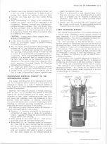
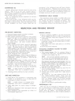
J-8393 C H A R G IN G STATION
The J-8393 Charging Station is a portable assembly of
a vacuum pump, refrigerant supply, gauges, valves, and
most important, a five (5) pound metering refrigerant
charging cylinder. The use of a charging cylinder elim
inates the need for scales, hot water pails, etc.
The chief advantage of this unit is savings. A very
definite savings in refrigerant and time can be obtained
by using this unit. Since the refrigerant is metered into
the system by volume, the correct amount may be added
to the system. This, coupled with the fact that the unit
remains "plumbed" at all times and thus eliminates loss
of refrigerant in purging of lines and hooking-up, com
bines to enable the operator to get full use of all re
frigerant purchased.
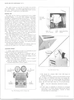
All evacuation and charging equipment is hooked to
gether in a compact portable unit (fig. 21). It brings air
conditioning service down to the basic problem of hooking
on two hoses, and manipulating clearly labeled valves.
This will tend to insure that the job will be done without
skipping operations. As a result, you can expect to save
time and get higher quality work, less chance of an over
or undercharge, or comeback.
M A IN T A IN IN G CHEMICAL STABILITY IN THE
REFRIGERATION SYSTEM
The metal internal parts of the refrigeration system
and the refrigerant and oil contained in the system are
designed to remain in a state of chemical stability as
long as pure R-12 and uncontaminated refrigeration oil
is used in the system.
However, when abnormal amounts of foreign materials,
such as dirt, air or moisture are allowed to enter the
system, the chemical stability may be upset. When ac
celerated by heat, these contaminants may form acids
and sludge and eventually cause the breakdown of com
ponents within the system. In addition, contaminants
may affect the temperature-pressure relationship of R-12,
resulting in improper operating temperature and pres
sures and decreased efficiency of the system.
The following general practices should be observed to
insure chemical stability in the system.
• Whenever it becomes necessary to disconnect a
refrigerant or gauge line, it should be immediately
capped. Capping the tubing will also prevent dirt and
foreign matter from entering.
• Tools should be kept clean and dry. This also in
cludes the gauge set and replacement parts.
• When adding oil, the container should be exception
ally clean and dry due to the fact that the refrigera
tion oil in the container is as moisture-free as it is
possible to make it. Therefore, it will quickly ab
sorb any moisture with which it comes in contact.
For this same reason the oil container should be
Fig- 21—
J-8393 Charging Station
HIGH PRESSURE
CONTROL (2)
LO W PRESSURE
CONTROL (1)
FREON
CONTROL
(4)
HIGH PRESSURE
G A U G E LINE
5 LB. C H A R G IN G
CYLINDER
LEAK
DETECTOR
FREON DRUM
CONTROL VALVE
V AC U U M
CONTROL
(3)
LOW
G A U G E LINE
OIL
INJECTOR
10-30 CHEVROLET TRUCK SERVICE MANUAL
Содержание 10 1971 Series
Страница 1: ......
Страница 96: ......
Страница 100: ...10 30 CHEVROLET TRUCK SERVICE MANUAL Fig 4 10 30 Series Truck Frame FRAME 2 4 ...
Страница 120: ......
Страница 203: ...ENGINE 6 25 Fig 22L Engine Mounts 10 30 CHEVROLET TRUCK SERVICE MANUAL ...
Страница 215: ...ENGINE 6 37 REAR M O U NT Fig 21V Engine Mounts 10 30 CHEVROLET TRUCK SERVICE MANUAL ...
Страница 218: ......
Страница 249: ......
Страница 250: ...EMISSION CONTROL SYSTEMS 6T 4 Fig 3 Combination Emission Control System Routing V8 10 30 CHEVROLET TRUCK SERVICE MANUAL ...
Страница 324: ......
Страница 339: ...FUEL TANK AND EXHAUST SYSTEMS 8 15 SPECIAL TOOLS Fig 22 Special Tools 1 J 23346 Fuel Tank Gauge Remover and Installer ...
Страница 340: ......
Страница 365: ...10 30 CHEVROLET TRUCK SERVICE MANUAL Fig 43 Power Steering Pump M ounting STEERING 9 25 ...
Страница 368: ......
Страница 386: ......
Страница 390: ...ELECTRICAL BODY AND CHASSIS 12 4 10 30 CHEVROLET TRUCK SERVICE MANUAL ...
Страница 391: ......
Страница 392: ...ELECTRICAL BODY AND CHASSIS 12 6 Fig 5 Rear Lighting Composite 10 30 CHEVROLET TRUCK SERVICE MANUAL ...
Страница 409: ...ELECTRICAL BODY AND CHASSIS 12 23 Fig 27 Engine Compartment CA30 02 10 30 CHEVROLET TRUCK SERVICE MANUAL ...
Страница 410: ...ELECTRICAL BODY AND CHASSIS 12 24 18DK GRN 19 Fig 28 Instrument Panel CA30 02 10 30 CHEVROLET TRUCK SERVICE MANUAL ...
Страница 411: ...ELECTRICAL BODY AND CHASSIS 12 25 Fig 29 Instrument Panel CA30 02 10 30 CHEVROLET TRUCK SERVICE MANUAL ...
Страница 412: ...ELECTRICAL BODY AND CHASSIS 12 26 fh Ar r kk 4 Fig 30 Engine Compartment C A K A 10 20 CA30 03 z _ ...
Страница 416: ...ELECTRICAL BODY AND CHASSIS 12 30 Fig 34 Engine Compartment CA KA10 20 CA30 04 10 30 CHEVROLET TRUCK SERVICE MANUAL ...
Страница 420: ...ELECTRICAL BODY AND CHASSIS 12 34 Fig 38 Engine Compartment C A K A 1 0 20 06 16 10 30 CHEVROLET TRUCK SERVICE MANUAL ...
Страница 422: ...ELECTRICAL BODY AND CHASSIS 12 36 Fig 40 Instrument Panel C A K A 10 20 06 16 10 30 CHEVROLET TRUCK SERVICE MANUAL ...
Страница 423: ...ELECTRICAL BODY AND CHASSIS 12 37 Fig 41 R ear Lamps C A K A 1 0 20 06 16 10 30 CHEVROLET TRUCK SERVICE MANUAL ...
Страница 424: ...ELECTRICAL BODY AND CHASSIS 12 38 Fig 42 Engine Compartment CA KA10 20 CAl30 14 34 10 30 CHEVROLET TRUCK SERVICE MANUAL ...
Страница 426: ...ELECTRICAL BODY AND CHASSIS 12 40 Fig 44 Instrument Panel CA KA10 20 CA30 14 34 10 30 CHEVROLET TRUCK SERVICE MANUAL ...
Страница 428: ......
Страница 432: ......
Страница 449: ...SPECIFICATIONS 9 10 30 CHEVROLET TRUCK SERVICE MANUAL ...
Страница 463: ......
Страница 464: ......
Страница 465: ......
Страница 466: ......