


CLUTCHES AND TRANSMISSIONS 7-24
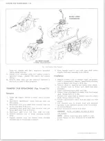
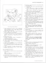
8. Reinstall transmission support crossmember to
adapter and frame.
9. Install transmission to transfer case adapter attach
ing bolts (torque to 21 to 29 ft. lbs.) and remove lift
equipment.
10. Connect front and rear axle prop shafts to transfer
case.
11. Install exhaust system crossover pipe.
12. Connect manual control lever rod and detent cable to
transmission.
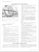
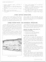
OTHER SERVICE
Although certain operations, such as oil pan gasket or
manual levers and oil seal replacement, detent cable,
governor, filler pipe “ O” ring, speedometer drive gear,
case extension “ 0 ” ring and rear oil seal, vacuum
modulator, and intermediate clutch accumulator cover
service may be performed from underneath the vehicle
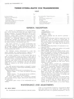
TURBO HYDRA-M ATIC 350
Accurate diagnosis of transmission problems begins
with a thorough understanding of normal transmission
operation. In particular, knowing which units are in
volved in the various speeds or shifts so that the specific
units or circuits involved in the problem can be isolated
and investigated further. Analytical diagnosis will pro
tect the technician from come backs and certainly will
improve owner satisfaction.
An important and often overlooked aspect of diagnosis
is finding out specific customer complaints. For this
purpose a short ride with the customer will often prove
beneficial. It may be found that the condition the custom
er wants corrected is standard and should not be altered.
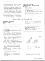
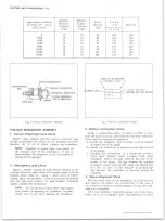
Fig„ 5 —*Pressure Tap Locations
13. Connect vacuum modulator line and speedometer
drive cable to transmission.
14. Assemble rod on transfer case shift lever before
installing rod to transfer case shift linkage. Torque
shift lever attaching bolt to 40-45 ft. lbs.
15. Lower vehicle and remove from hoist.
16. Refill transmission through filler tube following the
recommended procedure outlined in this Section.
17. Check transmission for proper operation and for
leakage. Check, and if necessary, adjust linkage.
OPERATIONS
without removing the Turbo Hydra-Matic 350; their
service procedure is covered in the Overhaul Manual and
is not repeated here. Refer to the Turbo Hydra-Matic
350 Section of the Overhaul Manual for all other service
operations not covered here.
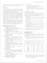
DIA G N O SIS PROCEDURE
The following sequence, based on field experience, pro
vides the desired information quickly and in most cases
actually corrects the malfunction without requiring the
removal of the transmission. Details of the items listed
in this sequence are covered further in the text.
SEQUENCE FOR TURBO HYDRA-MATIC 350
DIAG N OSIS PROCEDURE
1. Check oil level and condition.
2. Check and correct detent cable adjustment.
3. Check and correct vacuum line and fittings.
4. Check and correct manual linkage.
OIL LEVEL AN D CONDITION CHECK
Always check the oil level before road testing. Oil
must be visible on dip stick prior to operating the ve
hicle. Erratic shifting, pump noise, or other malfunc
tions can in some cases be traced to improper oil level.
Oil level should be checked with the selector lever in
the Park (P) position, engine running, and the vehicle on
level pavement.
Fluid level should be to the FULL mark with the trans
mission at normal operating temperature (170°-190°F.).
With warm fluid (room temperature), the level should be
at or 1/4 inch below the ADD mark.
If oil level was low, refer to Oil Leaks.
The condition of the oil is often an indication of whether
the transmission should be removed from the vehicle, or
to make further tests. When checking oil level, a burned
smell and discoloration indicate burned clutches or band
and the transmission will have to be removed.
M ANUAL LINKAGE
Manual linkage adjustment and the associated neutral
safety switch are important from a safety standpoint.
The neutral safety switch should be adjusted so that the
engine will start in the Park and Neutral positions only.
With the selector lever in the Park position, the park
ing pawl should freely engage and prevent the vehicle
10-30 CHEVROLET TRUCK SERVICE MANUAL
Содержание 10 1971 Series
Страница 1: ......
Страница 96: ......
Страница 100: ...10 30 CHEVROLET TRUCK SERVICE MANUAL Fig 4 10 30 Series Truck Frame FRAME 2 4 ...
Страница 120: ......
Страница 203: ...ENGINE 6 25 Fig 22L Engine Mounts 10 30 CHEVROLET TRUCK SERVICE MANUAL ...
Страница 215: ...ENGINE 6 37 REAR M O U NT Fig 21V Engine Mounts 10 30 CHEVROLET TRUCK SERVICE MANUAL ...
Страница 218: ......
Страница 249: ......
Страница 250: ...EMISSION CONTROL SYSTEMS 6T 4 Fig 3 Combination Emission Control System Routing V8 10 30 CHEVROLET TRUCK SERVICE MANUAL ...
Страница 324: ......
Страница 339: ...FUEL TANK AND EXHAUST SYSTEMS 8 15 SPECIAL TOOLS Fig 22 Special Tools 1 J 23346 Fuel Tank Gauge Remover and Installer ...
Страница 340: ......
Страница 365: ...10 30 CHEVROLET TRUCK SERVICE MANUAL Fig 43 Power Steering Pump M ounting STEERING 9 25 ...
Страница 368: ......
Страница 386: ......
Страница 390: ...ELECTRICAL BODY AND CHASSIS 12 4 10 30 CHEVROLET TRUCK SERVICE MANUAL ...
Страница 391: ......
Страница 392: ...ELECTRICAL BODY AND CHASSIS 12 6 Fig 5 Rear Lighting Composite 10 30 CHEVROLET TRUCK SERVICE MANUAL ...
Страница 409: ...ELECTRICAL BODY AND CHASSIS 12 23 Fig 27 Engine Compartment CA30 02 10 30 CHEVROLET TRUCK SERVICE MANUAL ...
Страница 410: ...ELECTRICAL BODY AND CHASSIS 12 24 18DK GRN 19 Fig 28 Instrument Panel CA30 02 10 30 CHEVROLET TRUCK SERVICE MANUAL ...
Страница 411: ...ELECTRICAL BODY AND CHASSIS 12 25 Fig 29 Instrument Panel CA30 02 10 30 CHEVROLET TRUCK SERVICE MANUAL ...
Страница 412: ...ELECTRICAL BODY AND CHASSIS 12 26 fh Ar r kk 4 Fig 30 Engine Compartment C A K A 10 20 CA30 03 z _ ...
Страница 416: ...ELECTRICAL BODY AND CHASSIS 12 30 Fig 34 Engine Compartment CA KA10 20 CA30 04 10 30 CHEVROLET TRUCK SERVICE MANUAL ...
Страница 420: ...ELECTRICAL BODY AND CHASSIS 12 34 Fig 38 Engine Compartment C A K A 1 0 20 06 16 10 30 CHEVROLET TRUCK SERVICE MANUAL ...
Страница 422: ...ELECTRICAL BODY AND CHASSIS 12 36 Fig 40 Instrument Panel C A K A 10 20 06 16 10 30 CHEVROLET TRUCK SERVICE MANUAL ...
Страница 423: ...ELECTRICAL BODY AND CHASSIS 12 37 Fig 41 R ear Lamps C A K A 1 0 20 06 16 10 30 CHEVROLET TRUCK SERVICE MANUAL ...
Страница 424: ...ELECTRICAL BODY AND CHASSIS 12 38 Fig 42 Engine Compartment CA KA10 20 CAl30 14 34 10 30 CHEVROLET TRUCK SERVICE MANUAL ...
Страница 426: ...ELECTRICAL BODY AND CHASSIS 12 40 Fig 44 Instrument Panel CA KA10 20 CA30 14 34 10 30 CHEVROLET TRUCK SERVICE MANUAL ...
Страница 428: ......
Страница 432: ......
Страница 449: ...SPECIFICATIONS 9 10 30 CHEVROLET TRUCK SERVICE MANUAL ...
Страница 463: ......
Страница 464: ......
Страница 465: ......
Страница 466: ......