24
a) Electrode shall be replaced when the instrument is shutdown. In case of the discharge, the high
voltage up to thousands of volts on the electrodes will cause great harm to the human body.
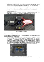
b) Open the windshield to present the electrode as shown in Fig.24;
c) First loosen the screws of electrode cap, take off the electrode cap and take out the electrode.
Prevent the electrode from falling into the fusion splicer. Place the new electrode in the electrode
holder slot, push the electrode forward to the end, and tighten the screws of electrode cap.
d) Replace the other electrode;
e) Start Discharge the battery several times or operate the electrode aging function in the menu
mode to stabilize the discharge of electrode. Then perform the discharge correction.
Fig.24 Electrode cap and screw
5.4 Adjustment of Electrode Holder
In case of the significant offset of discharge arc or the unstable discharge, the electrode holder shall be
readjusted according to the following steps:
a
)
Place a well-cut bare fiber into the V-groove to make the cut cross-section between the both
V-grooves if possible, and then gently press the fiber with a toothpick to make it completely drop
into the groove as shown in Fig.25 . At this time, observe whether the fiber cross-section is
positioned at the middle of electrode tips at both sides, and if not, loosen the screws of electrode
holder, and re-adjust the position of electrode holder to make the distance from the electrode
tips to fiber cross-section equal with that from the electrode tips to the V-grooves. Then press
[ARC] button to observe the position of fiber end and try to ensure it at the middle of arc.
Fig.25 Schematic diagram of electrode position adjustment
Electrode
cap
and screw
Содержание 6481 Series
Страница 8: ...6 Fig 4 Jam of propel motor...
Страница 11: ...9 Fig 8 Align motor Screws of align motor...
Страница 14: ...12 Fig 11 Imaging lamp Screws fixing the imaging lamp Cable at spindle may be damaged Weld point may be broken...
Страница 16: ...14 Fig 13 Replacement of spindle...
Страница 21: ...19 Fig 18 Main control panel FPGA load indicator V17 X4 socket...


